Showing posts with label 3D design. Show all posts

Monday, 19 October 2020

Ender 3 Upgrade: Dual Extrusion with SKR 1.3

Endurance ready to print
      Time for the reveal of a long-term project that's been around in various forms for a couple years, Duel-extrusion. Back in Febuary I'd started to experiment with converting my Ender 3 to dual-colour extrusion using a spare Lite6 hot-end and V6 clone that I found on Amazon.

Thing:3516409 mount
     Mounting the hot-ends for initial testing of the idea was fairly simple, there's lots of good mounts for V6 series hot-ends on Thingiverse, I specifically went with thing:3516409 to start with since it allows for reconfiguring from single to dual extrusion with only a couple printed parts as mounts. The next issue to tackle was electronics.

Ramps stack on Ender 3
     Now, the Ender 3 default electronics are fairly good for a basic single extrusion printer, but don't allow for duel nozzles, so I swapped the silent 1.1.4 board from my last upgrade out for a spare Ramps/Mega2560 stack that I normally use on my MPCNC. The Mega2560 isn't rated for 24V power but there is a fairly old work-around that solves this problem on the RepRap wiki, I then wired a spare LM2596 buck converter to provide the needed 12V power for the processor board's onboard regulator and the hardware side was ready for inital testing.

BigTreeTech SKR 1.3 with stepper drivers partially installed
    Unfortunately, this was right at the start of April 2020, so testing things out got put on hold until June since all of my printers were fabricating PPE gear as part of BCC3D.ca's efforts. This showed that Ramps at 24V is ok for short-term use, but I had one of my extruder stepper drivers blow out, so a better solution was needed for long-term usage. Some research on newer 32-bit boards showed that the BigTreeTech SKR 1.3 board fit the needs of this upgrade perfectly.

Custom dual hot-end mounts
    The other short-coming that was revealed was the dificulty in aligning the duel hot-ends correctly since this type of dual-extrusion setup needs the nozzles in the exact same horizontal plane or close enough to make no difference with the intended layer-height. The Thingiverse mount had both hot-ends locked at the same height at the top but not at the bottom, so I pulled a copy of the Ender 3 source-file into Fusion 360 and started drawing up a custom mount pair to fix the issue. 

Design in progress
     My solution to the problem has the right-hand hot-end at a fixed height bolted to the stock hot-end mount posts since that's the zero reference point for the entire printer coordinate system. The left hot-end is tucked into a dead-space on the side of the tool-plate that's normally used for mounting optional auto-levelling probes but is the exact right size to fit a V6 heat-sink while allowing both nozzles to reach the full width of the bed. With all that sorted out it was finally time to calibrate and try this out.

First Duel-extrusion print straight off the bed
     Now, obviously there's a fair bit of slicer tinkering needed to get a custom duel-extrusion system setup, so I loaded a couple lengths of scrap filament into the extruders and printed several test objects (thing:2388496, dual block object) to get the horizontal offsets correct in the firmware, then created a custom version of the Ender 3 profile in Prusa Slicer v22 with some custom startup gcode to get things heated correctly. Other than that I just turned the 'ooze shield' settings on, drew up a simple vase as a test part and turned it loose.

First dual-colour print after inital cleanup
     Clearly things aren't perfect, still some tuning with the retraction settings given the blobs all over the surface, but I'm quite pleased with how it turned out for a first print after all the work that's gone into this upgrade. The SKR board has proven quite robust and reliable, been running it non-stop for about 4-months now without issue so they're now my first choice for new printer controllers going forward.

Tuesday, 12 May 2020

Design Study: Castor wheels from scratch

PLA Wheel
      While working on another workspace upgrade project, I decided to try making my own castor wheels from scratch using some leftover bearings that were floating around in the parts bin. I started off from the known dimensions the castors that are on the bottom of my main workbench, about 1.5 inch tall, and the specs of the 625 bearings that I was planning to use.


Castor wheel parts version 1
     A bit of drafting in Fusion 360 ended up with the version 1 parts, they worked fairly well once assembled since I've done rotating parts with 625 bearings before, but they weren't rotating around the vertical pivot like I was expecting them to when turning, so what was going on? 

Castor wheel mounts version 3
     I pulled up some example of high-end castor wheels online and quickly found the two issues with my design that were causing the rotation to jam under load. First up is that commercial castors actually have the centre of mass/vertical rotation shaft centred over the outermost 25% of the wheel rim area. This means that the wheel is constantly trying and failing to escape from under the load, manifesting as the sideways force that makes the wheels rotate to the point of least resistance relative to where you're trying to move them. 

Castor wheel version 3 with bearing collar installed
     The second detail is a simple mechanical part choice to make sure the wheels don't bind or stick under the load they're rated for, a simple ring of ball bearings around the vertical shaft between the wheel bracket and mounting plate. It's sort of a knock-off 'thrust bearing' more than anything else, so I drew some modifications into the parts to create a 3D printable version for testing and light load applications. Current plans are to use these for a small storage cart for around my workshop, so more to come later this summer.

Finished castor wheel version 3

Friday, 17 May 2019

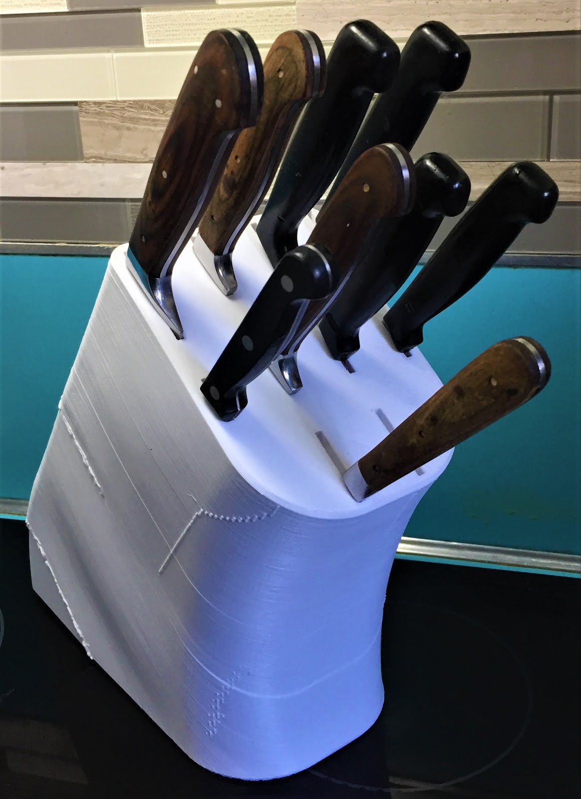
Household 3D Prints: Kitchen Knife Block

Kitchen Knife Block
    A few weeks ago I was washing some dishes in the kitchen and noticed the appalling state of the old wooden knife blocks, both were caked with dust and other debris, some seemed to have become ingrained into the finish, so I decided to 3D print a replacement that could actually hold all of the knives in a single block. The first step was looking at the full set to figure out what the basic sizes and styles were, came out as 2 cleavers, 5 regular ones, 2 pairing and 1 carving fork from a couple different sets. Most of them were fairly close in size for each type, so I took the length and width of the larges examples for each, then drew up a layout in Fusion 360.

Kitchen Knife Block in Fusion 360

     One issue that the old blocks had was it was difficult to access the handles for some of the knives due to the slots being tightly spaced, so I measured the handle widths and used double that dimension for the slot offset to fix this issue. Modelling the final form took about a day, then I loaded the model into my slicing program, ran the process with my standard settings and hit a snag. It was estimating over 1kg of PLA to print, and I didn't have any spools that big, so I decided to flip it on end and ditch the infill to see if that helped. It worked and got the weight down to 900g or so, so I turned it loose on the Mega Kossel with an almost full spool of PLA.

Finished Knife Block in use
    After almost 2 days of non-stop printing, it finished at 46 hours and an empty spool of PLA. I'd previously done a couple small prints with the reel, so I actually ended up doing the last 3 cm on the Ender 3 with another spool, then using my 3D pen to weld the 2 sections together. This thing is officially the single longest print I've ever done in the past 4 years, so I'm fairly pleased with how it turned out.

Tuesday, 30 October 2018

Household 3D printing round 3: Lampshades and Gardening

Greenhouse over planter box
     Been busy with helping wind-down the garden and cleaning up for the winter over the past couple of weeks, this included converting one of the beds into a mini-greenhouse. The core materials are 25-30 square meters of transparent plastic sheeting for the shell, a couple of 12 foot lengths of 1 inch plastic tubing and some 1/2 inch electrical conduit (EMT) off-cuts from the old Proteus build. Obviously this collection of components needs some way to connect everything, that's where 3D printing comes in with custom adapters and clamps.


Frame hoop anchor bracket with EMT  connector and plastic tubing.
      The frame is formed from the 1" plastic tubing with the EMT conduit used as corner posts that are anchored with connectors that I'd made for another project over the summer, basically a corner anchor to connect EMT to wood or other sheet material. Installation is fairly simple, two screws hold the bracket down to the planter box, then the EMT gets inserted the bracket and the plastic tube is slipped over the top to form the main arches. Cross bracing is provided by both the outer plastic sheeting and a cross-beam formed from some spare 1" tubing with more custom brackets.


Cross-beam connector in white PLA
     The outer plastic shell is held down by custom clips that clamp onto the 1" tubing in a 270° arc. So far it's stood up to a fairly intense rainstorm with minimal issues, a couple of the clips were overwhelmed by the wind and their position on the frame but it's easy to fix by printing slightly tighter ones for those spots.


Plastic sheet clamping clip in use
     The other project I've been working on is spiral lampshades using parametric design in Fusion 360, mainly as a way to learn more about the program and to replace a couple of ancient dust-trap shades that had gotten impossible to clean.

Twisty Lampshade fresh off the printer
    The form I settled on is a 7-sided cylinder, 25 cm tall and 19 cm in diameter. I started with a lofted form to create the slight curve to the sides and then hollowed it out to have 1.2mm thick sides for optimum light refraction. The material is basic white PLA without any heat-treatments or other modification after printing, and it's held up perfectly fine with an old incandescent bulb in the lamp.


Lamp with incandescent bulb and PLA shade.

Monday, 23 July 2018

Designing Custom Lens Adaptors for Vintage Lenses and Modern Digital Cameras

Vintage Lenses with 3D printed adaptors
    Recently I was commissioned to examine a collection of vintage lenses to see if it was possible to make adaptors to mount them on a FujiFilm X-E2 digital camera. The lenses were quite varied, a pair of 16mm film camera lenses, a microscope lens, and Meyer-Optik 400mm telephoto lens.


Lens adaptor for Meyer-Optik 400mm lens

Meyer-Optik 400mm lens with adaptor attached
   The 16mm lenses were a bit different and required custom adaptor plates to link them directly to the camera's mounting ring, so I set about figuring out the dimensions and best way to print them.

Wide-angle 16mm lens with 3D printed adaptor
     The 16mm lens set consisted of a wide-angle lens and a more general telephoto lens that had a damaged mounting ring, so I designed its mounting plate to include some M3 set-screws to secure it.

16mm telephoto lens with 3D printed adaptor plate and set-screws
     Lastly, the microscope lens was the trickiest since it has no focusing mechanism at all, so it's adaptor plate had to serve that function instead by incorporating a screw thread between the inner and outer sections.

Microscope Lens with focusing adaptor
     After further refining my basic design ideas, I'm now offering some basic sizes for sale on Shapeways:

Friday, 2 March 2018

Magnetic Print Bed Surface on a Budget

Mega Kossel with magnetic build plate
     When I rebuilt my Mini Kossel into the Mega Kossel last August, I installed upgraded rod-arms that allow for a maximum build diameter of 250mm (9.84 in), and I've been using a 190mm (7.5 in) piece of glass topped with Buildtak as my bed for the past 6 months, so I've really been using only 58% of my theoretical build diameter. I'd looked at upgrading the bed surface with the Buildtak Flexplate system in the past, but the only circular option currently available is a 300mm (12 in) set, far to large for my frame and 220mm heat-bed. Thus, I started looking at options for building my own custom version.


10-inch pizza lifter from the local dollar store
     Concept wise, the Flexplate system is fairly straightforward, an adhesive sheet with magnets in it that sticks to the printer's heat-bed or build plate, topped with a spring steel sheet with some Buildtak material on one side. For my version, I'm using some steel pizza lifters that I found at the local dollar store in the cooking supplies section of all things, $4 each and a bit of drilling to remove the riveted-on handle and I've got some fairly flat surface plates.


Adhesive backed magnets assortment from Lee Valley Tools
     For the magnetic part of things, I'm using some 6mm rare-earth magnets that I salvaged from an old toy building set that I had floating around, but Lee Valley sells some 1/4" ones that are a fairly close match. 


Bed mounting bracket with magnets installed
Other side of bed mount with magnets
I've designed a variation of the mounting brackets for my heat-bed that puts 36 of them in a ring around the entire bed, massive overkill when it comes to this type of magnet but having the bed surface start drifting loose is the last thing you want on a 3D printer of any type.

Corner brackets waiting for magnets
Brackets mounted on Mega Kossel
     After printing the brackets, I used some 5-minute epoxy to fix the magnets in place, I've found that it does an excellent job of holding parts to PLA prints under most conditions.


Magnetic bed fully installed on the Mega Kossel
     I've been using this bed configuration for the past 2 weeks already and it works quite well. This particular implementation is specific to the Mega Kossel, but if I was going to install something like this on an i3 style machine, I'd make custom brackets that put the magnets in a line along the front and back edges of the bed, then use a slightly oversize sheet of steel for the bed topping plate.

Saturday, 3 February 2018

Household 3D Prints Roundup 2

LED candle shrouds
     Been a while since I covered prints that I've put around the house, so here's some of the stuff that's been made over the past year. Starting with the above, those are simple spiral vase prints that have a small LED tea light inside for decoration. Design wise, they're really simple, just a faceted cylinder with lots of extra horizontal rings twisted along it's vertical axis, I used Wings 3D 2.1.5 as my design program of choice here. Filament is MG Chemicals Gold PLA, prints look like natural beeswax in colour, really nice for making decorative shades and such.


Toothbrush Holders
     Not the kind of thing you'd expect to use transparent PLA vase-mode prints for, but the faceted spiraling makes them surprisingly sturdy for this kind of use. Again, custom designs done in Wings 3D, using 3D Solutech Natural PLA this time, all printed on the Mega Kossel.

Birdseed filter in use
Birdseed filter clean
Birdseed filtering funnel
     Next up is something bird related, I've got a couple of budgies that are rather picky eaters, they don't like large sunflower seeds and keep emptying the food dish onto the floor if the find them. My solution to the problem is to design a funnel with a removable filter grate that strains the largest seeds out but lets all of the smaller stuff through. It's a simple design, just a cone with a 2 cm cylinder stuck on the point and hollowed out to about 3mm thick walls, the real trick is that rather than modeling the final grill in the CAD software, I just modeled the outer dimensions for it and used the infill settings in my slicer software to create the grid. I'm using Slic3r for my slicing program and the filter grid is the result of using 10% rectangular infill with zero top and bottom layers.

Towel hook on bathroom door
    And finally, this is the current iteration of the Customisable U-Hook from Thingiverse that's being used as a towel hook on the bathroom door. It's printed in MG Chemicals PETG for strength, the previous ones were in PLA and both snapped after about 6-9 months of daily use, this one is currently at 5 months and counting, be interesting to see how it holds up after a year of use. And in closing, I redid the oven knob from last time, the original part wasn't thick enough on the walls for the adaptor plug and failed after about a year of use. the current one was made in one piece with a thicker walled plug and is still going strong after about 9 months of regular use.

Oven knob V2

Thursday, 30 November 2017

Flying extruders and Deltas, Round 2

Mini Kossel and Mega Kossel with Flying Extruders
     Back in February, I tried installing a flying extruder on my Mini Kossel, didn't work out very well because one of the carriages would randomly slip during the first few layers of a print and suddenly it was air-printing and making a complete mess. So I switched back to the normal extruder configuration and kept it that way until I built the Mega Kossel

Mega Kossel Flying extruder V2
    For this version I decided to use elastic bands to hold everything in place, worked a bit better but still hit the same issue of random carriage slips. After watching it do this a couple of times I realised that the root cause was the extruder assembly's inertia damping the carriage movement and overwhelming the motor on the tower, causing the drive belt to slip on the pulley and produce the effect I'd been seeing. At that point I was just trying to get the new printer working, so I striped the flying extruder components off and set things up for a conventional long Bowden system. Further research into Kossel design was obviously needed to sort out what the solution to the issue was.

34mm (left) & 48mm (right) NEMA 17 stepper motors
    It was while building the Sculptor that I finally figured out the issue, it was the NEMA17/34mm steppers that were originally part of my Mini Kossel kit that were the root cause of the problem. Like most ~$300 kits, it had fairly light stepper motors for powering the motion mechanics, and while they were sufficient for normal use, I'd found some old forum posts that recommended longer NEMA17/48mm steppers for use on delta printers, and indeed I'd followed that advice when building the Micro Kossel in the first place, so I did a motor transplant and installed the 48mm motors on the Mega Kossel. The difference was quite noticeable once I powered it up and homed the effector. With the original motors it was possible to shake the effector about 3mm sideways even with the motors powered up, with the new ones the effector felt like it was glued in place, zero wobble or shake that I could detect. 
Mega Kossel Flying Extruder V2
    I used the Mega in that state until early November, then decided to try the flying configuration again. Surprisingly, it worked perfectly even without the counterweight that I'd used in the previous versions so I decided to stay with this version for the foreseeable future. 
Mega Kossel with flying extruder

Tuesday, 18 July 2017

Summer Project: Upgrading the workshop

Workshop upgrades
     My workspace has been getting into a bit of a mess over the past year, so it was time for a cleanup this summer and I've ended up building a couple small projects to help with reorganizing. One's a cart for the spare that was piling up in one corner, the second is a small router table to help with the third which is a tool chest for storing all the small hand tools.

Wood Cart Concept
     The worst of the mess was, not surprisingly, the wood pile. After watching this YouTube video, I decided that building something like it would be the best solution for my own wood pile. Starting with Fusion 360, I drew up rough plans for a wood cart that could handle anything up to half a sheet of plywood, that's the largest piece of wood that I've got space to work with. After a trip to Home Depot to get some wood for the frame, I ended up building the final cart from a 2'x4' 1/4 sheet of plywood for the base, 4 8'x2"x2" composite posts cut to 5' and 3' sections, 4 casters, and a couple of old IKEA storage boxes that were in the shop. The Fusion 360 file is here.

Wood Cart as built with MPCNC in background
Router Table
    With the wood pile sorted, the next area that needed reorganizing was the hand tools. Previously I had them in the upper trays from some old tool boxes on a long shelf about 12 inches above one of the work benches, didn't work that great with the tools constantly getting mixed up and covered in sawdust. After seeing some YouTube videos of other tool organizing methods, I drew up a concept for a wooden tool chest in Fusion 360. (File)

Tool Chest Concept
     One issue with the design that was immediately apparent was that I'd need some form of jig or tool to cut the slots in the sides for the drawer bottoms, which double as the drawer slides, to run in. I've seen slots like this cut in a few ways on YouTube, a Dado blade set with a table saw or a router table are the most common options. I don't have a dado set but I did have a spare plunge router that was just gathering dust, so I made a simple table for it out of some stuff that was lying around the shop.

Router mounting system
Power management
     I used an old folding worktable for the legs, bolted a 2ft by 2ft square of sanded plywood on for a top. For mounting the router, I used a skill saw to cut a hole in the top that the plunge router would fit through, then used the MPCNC palm router to cut a shallow groove that would allow a 1/4" sheet of hardboard to sit flush with the top, then cut a piece to fit and screwed the router to one side after drilling a 2-inch hole for the bit to pass through. After that it was a simple matter of dropping the router through the hole, sanding the top completely flat, and dealing with the power wiring. Since the plunge router has its trigger mounted on one of the hand grips, I simply used its lock-on function to bypass it and zip-tied an old power bar to the side, plug the router into that and it functions as a on/off switch.

Tool Chest as built
     With the router table complete, it was a simple matter of firing up the table saw and cutting all the pieces of plywood and hardboard to size, using the router table to cut the slots for the drawers, and then screwing everything together. I did use a hole saw bit on the drill press to cut the notches for the drawer handles, but that was basically it for making the tool chest, and I'm very pleased with the result of both projects.