Showing posts with label 32-bit electronics. Show all posts

Monday, 19 October 2020

Ender 3 Upgrade: Dual Extrusion with SKR 1.3

Endurance ready to print
      Time for the reveal of a long-term project that's been around in various forms for a couple years, Duel-extrusion. Back in Febuary I'd started to experiment with converting my Ender 3 to dual-colour extrusion using a spare Lite6 hot-end and V6 clone that I found on Amazon.

Thing:3516409 mount
     Mounting the hot-ends for initial testing of the idea was fairly simple, there's lots of good mounts for V6 series hot-ends on Thingiverse, I specifically went with thing:3516409 to start with since it allows for reconfiguring from single to dual extrusion with only a couple printed parts as mounts. The next issue to tackle was electronics.

Ramps stack on Ender 3
     Now, the Ender 3 default electronics are fairly good for a basic single extrusion printer, but don't allow for duel nozzles, so I swapped the silent 1.1.4 board from my last upgrade out for a spare Ramps/Mega2560 stack that I normally use on my MPCNC. The Mega2560 isn't rated for 24V power but there is a fairly old work-around that solves this problem on the RepRap wiki, I then wired a spare LM2596 buck converter to provide the needed 12V power for the processor board's onboard regulator and the hardware side was ready for inital testing.

BigTreeTech SKR 1.3 with stepper drivers partially installed
    Unfortunately, this was right at the start of April 2020, so testing things out got put on hold until June since all of my printers were fabricating PPE gear as part of BCC3D.ca's efforts. This showed that Ramps at 24V is ok for short-term use, but I had one of my extruder stepper drivers blow out, so a better solution was needed for long-term usage. Some research on newer 32-bit boards showed that the BigTreeTech SKR 1.3 board fit the needs of this upgrade perfectly.

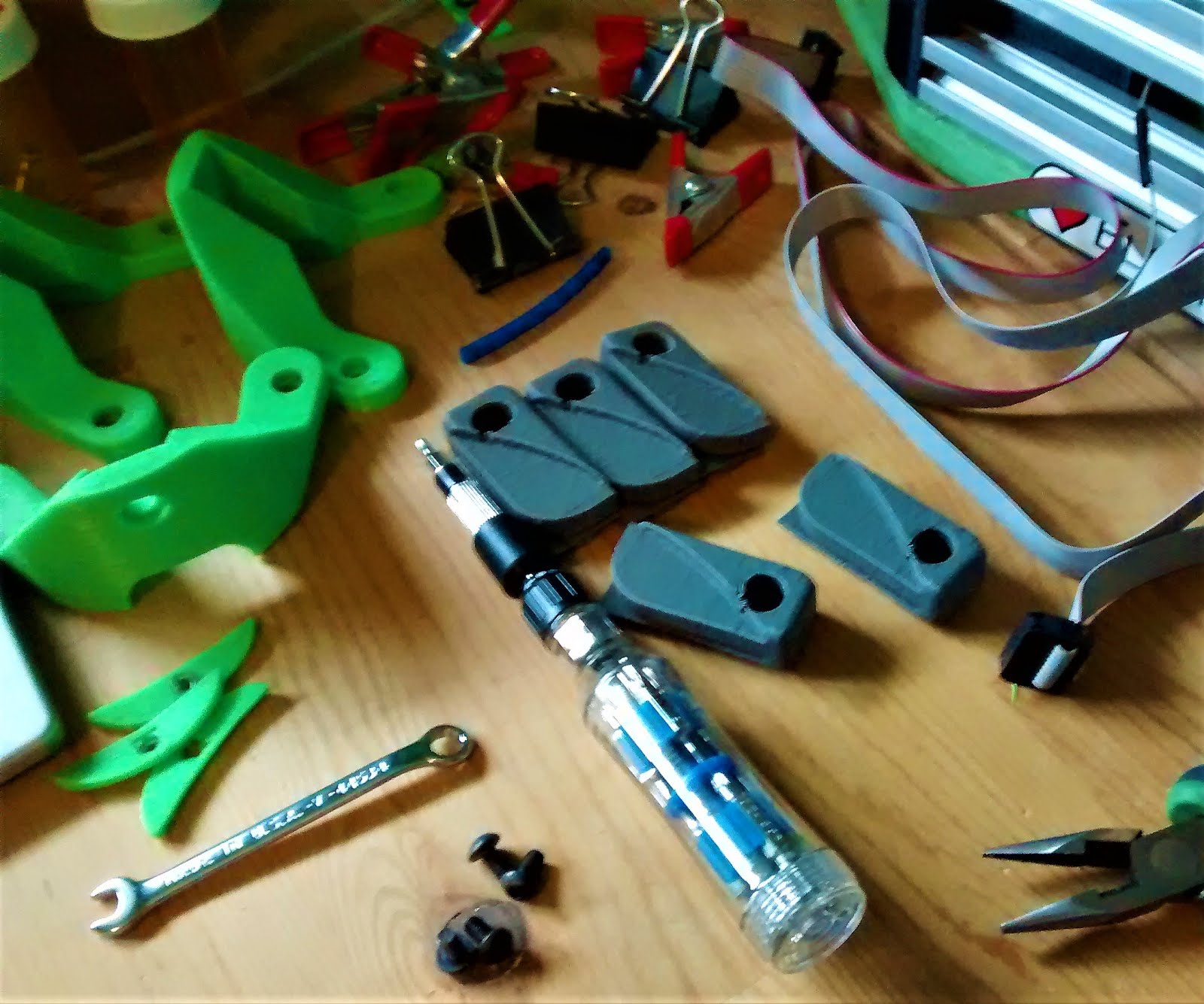
Custom dual hot-end mounts
    The other short-coming that was revealed was the dificulty in aligning the duel hot-ends correctly since this type of dual-extrusion setup needs the nozzles in the exact same horizontal plane or close enough to make no difference with the intended layer-height. The Thingiverse mount had both hot-ends locked at the same height at the top but not at the bottom, so I pulled a copy of the Ender 3 source-file into Fusion 360 and started drawing up a custom mount pair to fix the issue. 

Design in progress
     My solution to the problem has the right-hand hot-end at a fixed height bolted to the stock hot-end mount posts since that's the zero reference point for the entire printer coordinate system. The left hot-end is tucked into a dead-space on the side of the tool-plate that's normally used for mounting optional auto-levelling probes but is the exact right size to fit a V6 heat-sink while allowing both nozzles to reach the full width of the bed. With all that sorted out it was finally time to calibrate and try this out.

First Duel-extrusion print straight off the bed
     Now, obviously there's a fair bit of slicer tinkering needed to get a custom duel-extrusion system setup, so I loaded a couple lengths of scrap filament into the extruders and printed several test objects (thing:2388496, dual block object) to get the horizontal offsets correct in the firmware, then created a custom version of the Ender 3 profile in Prusa Slicer v22 with some custom startup gcode to get things heated correctly. Other than that I just turned the 'ooze shield' settings on, drew up a simple vase as a test part and turned it loose.

First dual-colour print after inital cleanup
     Clearly things aren't perfect, still some tuning with the retraction settings given the blobs all over the surface, but I'm quite pleased with how it turned out for a first print after all the work that's gone into this upgrade. The SKR board has proven quite robust and reliable, been running it non-stop for about 4-months now without issue so they're now my first choice for new printer controllers going forward.

Saturday, 13 May 2017

Project: Proteus Delta, part 8

Proteus Delta with Prometheus System installed
     Last time with the Proteus Delta I'd just installed the heat-bed, then left it sitting for a few months while waiting on delivery of the Prometheus System by Distech Automation, which is a dual extruder/single hot-end printing system that allows for the use of 2 different materials or different colours of the same material in a single print.


Prometheus System half assembled with parts of effector platform
     After receiving the parts for the Prometheus system at the beginning of April, assembly took a week or so of evenings working on assembly, partially because I got the parts for both the original design and the revisions that occurred after the 'early-bird/beta' system feedback was received. So, since I had the original PEEK feed pipe, the splitter fork got assembled as per the original design instructions, and the extruders are using the revised design with the reinforced Bowden clamps.


Prometheus hot-end installed in effector
     For actually mounting the Prometheus system on the Proteus, I'd designed a custom raised effector shell back in November, after giving it a final polishing pass, the parts got printed and bolted together. I'm still working on the part-cooling fan ducting but the rest of the parts are here.


Effector installed on Proteus for initial testing
     After installing the completed effector on the Proteus, I started moving the motion system around by hand to check for any issues, and it immediately became apparent that the clamps that were holding the print-bed in place where going to cause issues with the effector since the hot-end tip is only slightly below the effector ring. 


Proteus print-bed with new mounts
      After some revising, reprinting and reassembly, the problem was mostly solved by switching to a new mounting bracket design for the print-bed, the STL is here, it's designed to grip the glass along the side and recess the mounting screw flush with the upper surface, allowing for a 28cm maximum printing diameter, although I would recommend printing it in a high-temperature resistant plastic, otherwise the bed will start drifting when you go past the glass-transition temperature.


Effector mounting plate and spool holder hardware waiting for assembly
     Originally, I was planning to mount the ProStruders in a flying configuration, but after February's experiments, I've decided to put them on an independent pylon, roughly 46 cm down from the top, mostly level with the effector when it's homed. For holding the spools, I'm using one of the leftover sections of 1/2inch EMT from building the towers, it's the perfect length for sticking a pair of spools on, one on each side above the extruders. Add some printed caps and a clamp to keep things in place, and that finishes the assembly process.


Extruders mounted to Proteus with spool holder above
Proteus Delta ready to print
     With all that finished, the next step was calibration and a couple of test prints. Leveling the bed was mostly the same as I've covered previously, only real change was initial setup of the SD card for the Duet 0.8.5, most of the files are linked through the Duet wiki, but one really useful tool is the Reprap Firmware Configurator, it has a couple of quirks, specifically the default thermistor for heatbeds is wrong, but makes most of the configuration process fairly painless overall. I'm still getting the hang of using it, but the few prints I've done so far are fairly good for PLA without a part cooling fan. Overall, a fun build and I'm looking forward to trying some dual colour prints in the near future.

Tuesday, 24 January 2017

Re-ARM of a Mini Kossel

Panucatt Devices Re-ARM board Bottom View
     Last month, I covered some of the key upgrades on my mini Kossel, and most of them were things that improve the extrusion path. This time, I'm switching the controller board from an 8-bit Arduino Mega 2560 to a new 32-bit Smoothieware-based board called the Re-ARM for Ramps

New and Old: Re-ARM/Ramps (top right), Arduino Mega2560 (bottom left)
     Physically installing the Re-ARM was fairly simple, I just needed to remove the print bed and lift the Ramps assembly out from underneath. After that, a few minutes work with some pliers to gently separate the Mega and Ramps boards, then mount on the Re-ARM's headers with some gentle pressure until things are snug. Don't forget to set the Re-ARM's power mode before installing the Ramps, it's impossible to change the jumper with it in-place.
Re-ARM/Ramps with mounting bracket (on the left)
     After assembling the boards, I found that my Mega2560 mount was incompatible with the Re-ARM's footprint - mostly just a tolerances issue, the mounting bracket I was using is a bit sloppy, so I loaded the Re-ARM's digital reference into Fusion 360 and drew up the bracket above. It's designed to raise the Re-ARM to just the right height to allow the optional Ethernet adaptor to pass between the 2020 t-slot extrusions on the Kossel's base, and bolts down with a couple of #6 or M4 wood screws. The STL for it is here


Re-ARM/Ramps mostly installed
    Once the main boards where installed, it was time to add the graphics display. With the Arduino Mega, I'd used a Smart Controller display panel, but it wasn't compatible with the Re-ARM so I swapped it out for a Full Graphics Controller instead. The only real gotcha with using this display on the Re-ARM is that you need to splice part of the EXT2 cable to tap into one of the 5V rail pins since the main logic rails are operating at 3.3V.


Spliced line on EXT2 cable, it's the edge opposite the red reference line
5V pin for EXT2 splice


     And with that plugged in, I used the Micro Kossel to print some mounting brackets from Thingiverse for the display and then used some M3x20mm screws to install them.


Full Graphic Controller with Mounting brackets waiting for installation
Using zip-ties for cable management, helps keep things nice and tidy
Bracket fully installed using M4x0.8mm cap screw and M4 hex nut


     With that installed, all that's left is to remount the print-bed and deal with the software side of things. I'd originally used 3 M3x20 screws to hold the print-bed down, but these made it very vulnerable to warping and difficult to level after a reinstall, essentially requiring recalibration every time I needed to access the electronics. After running across thing: 1982435, I decided to make my own version with an extra slot for my heat shielding. Files are here.

Print-bed mounting blocks waiting for install
Test fitting heat shield
Finalizing exact positioning, note the M3x20mm screw and bolt for holding glass
     After sorting the heat shield, I still had a minor issue with the bed trying to float on top of the mounts, so I drafted up some extra wide M4 washers to hold things in place with some spare M4x20mm bolts I had left over from another project. You can see the floating issue in the next picture's lower left corner.


M4x20 bolts and custom washers waiting for final installation
Glass holder clip with M3 thumb wheel for holding the 195mm glass down
     As for holding the Buildtak/glass plate combo I use for an actual print surface onto the print-bed, my glass is an odd 195mm diameter, not the more standard 200mm or 220mm that you normally see, so the glass clips are customized for it. With that installed, it was largely just a matter of learning how to configure Smoothieware with the Mini Kossel's parameters, the official documentation, combined with the Re-ARM's setup guide were fantastic on this, then the usual calibration and it's done.


Retrofit complete, ready to print