|
| Mini Kossel |
This time I'm upgrading the printer I started out with, a basic Mini Kossel kit, to a larger and taller frame. After replacing the original wheels with steel wheels last year, the aluminum towers finally wore down to the point that one of the carriages basically fell off the tower.
The obvious choice for replacing the damaged towers was OpenBuilds V-slot, same outer dimensions as the original extrusions allowing reuse of the printed frame parts. I also ended up swapping the steel wheels with the Delrin versions, don't want a repeat of what happened to the old towers.
Since I was upping the size of the frame anyway, I cut the old towers down into new sides for the bottom triangle, the idea was to allow for mounting the power supply under the bed with the rest of the electronics, as well as allowing for upgrading the build plate in the future. Dimension wise, the side rails are now 30 cm long, allowing for anything up to a 25cm build plate. Reassembly was mostly the same as the original build process, just scaled up by a large margin.
I did learn some new tricks to make assembly more precise, probably the most useful was using a spare section of extrusion to set the end-stop height to exactly below the upper triangle. All that's needed for this trick is a 3-inch C clamp, a spare or unused piece of the extrusion and the end-stop assembly.
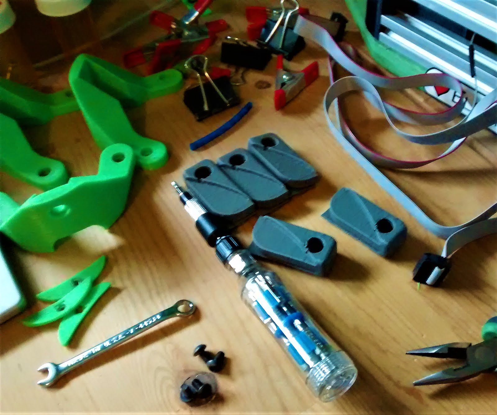
Once the frame was rebuilt, the other parts that needed replacement were the rod-arms, the originals were both too short for the new size and one was cracked after a rather spectacular malfunction last fall. For the new rod-arms, the parts list is quite simple, 12 Traxxas 5347 joints (Amazon.ca), 6 12" lengths of 8-32 threaded rod, an 8-32 tap and AndrewBCN's assembly tool (Thingiverse, thing:701248). The 8-32 tap is optional, it just makes assembly easier by pre-cutting the first couple turns of the thread in the Traxxas joints.
With the new rod-arms done, the next step was reinstalling the electronics and print bed. Since I'm not replacing the current print bed, some new mounts were needed, along with a new mounting bracket for the Re-ARM/Ramps boards. After creating a Fusion 360 mock-up of the bottom triangle, it was fairly easy to design new mounting brackets for the print bed, the Re-ARM was even simpler since the manufacture provides a cad file of the boards physical layout. The resulting STLs are here for download.
As you can see, the power supply ended up under the bottom triangle, just wasn't space for the control boards otherwise. The brackets I've designed for mounting the power supply are in with the other STLs above, you'll need to mirror file with your slicer program to get both the left and right versions. Only other parts needed for mounting are some M4x20mm screws and the power supply, I'm using this one, but the brackets should work for any similar module.
One of the recent improvements for deltas that's been trending on the net lately is adding protective covers to the corners over the lower pulleys and electronics bay. I've been meaning to add them for a while and came up with a simple way to make them out of some spare foam core.
Yep, that's it, just stick the printer on the foam core and trace around the base with a marker. I also used an earlier version of the print bed supports to center it under the printer frame and then traced it out as well. After that it was just putting the printed parts in their approximate spots, trace the outlines and then cut out the section that's left. I did use a drill to put 3 holes in each for ventilation over the motors but that was basically it. last step was wrap the edges with electrical tape for safety and colour the top black for aesthetics.
Now, obviously the power supply is currently serving as the structural base for the entire frame, not the best idea for long term stability or noise. I found these tennis ball feet (thing:2158108) on Thingiverse, they're printable adaptors that let 3 standard tennis balls serve as vibration damping feet, so I used the Micro Kossel to print a set and installed them.
And that was pretty much it, only things left to do were recalibration running a few test prints which turned out nicely.
 |
| 2020 Aluminum extrusion after running steel wheels for 14 months |
 |
| Enlarged upper triangle |
 |
| Enlarged lower triangle |
Since I was upping the size of the frame anyway, I cut the old towers down into new sides for the bottom triangle, the idea was to allow for mounting the power supply under the bed with the rest of the electronics, as well as allowing for upgrading the build plate in the future. Dimension wise, the side rails are now 30 cm long, allowing for anything up to a 25cm build plate. Reassembly was mostly the same as the original build process, just scaled up by a large margin.
 |
| Upgraded frame |
 |
| The simple way to set endstop height |
Once the frame was rebuilt, the other parts that needed replacement were the rod-arms, the originals were both too short for the new size and one was cracked after a rather spectacular malfunction last fall. For the new rod-arms, the parts list is quite simple, 12 Traxxas 5347 joints (Amazon.ca), 6 12" lengths of 8-32 threaded rod, an 8-32 tap and AndrewBCN's assembly tool (Thingiverse, thing:701248). The 8-32 tap is optional, it just makes assembly easier by pre-cutting the first couple turns of the thread in the Traxxas joints.
 |
| Parts for new rod-arms with completed arm |
 |
| Re-ARM and electronics installed |
 |
| Power supply mounting bracket |
 |
| Mounting bracket installed on power supply |
As you can see, the power supply ended up under the bottom triangle, just wasn't space for the control boards otherwise. The brackets I've designed for mounting the power supply are in with the other STLs above, you'll need to mirror file with your slicer program to get both the left and right versions. Only other parts needed for mounting are some M4x20mm screws and the power supply, I'm using this one, but the brackets should work for any similar module.
 |
| Print bed installed with dust covers |
 |
| Kossel on foam core for tracing |
 |
| Kossel and Print bed outlines on foam core |
 |
| Corner covers finished and installed |
Now, obviously the power supply is currently serving as the structural base for the entire frame, not the best idea for long term stability or noise. I found these tennis ball feet (thing:2158108) on Thingiverse, they're printable adaptors that let 3 standard tennis balls serve as vibration damping feet, so I used the Micro Kossel to print a set and installed them.
 |
| Tennis ball feet 2/3 installed |
 |
| Completed Mega Kossel |