Showing posts with label Build Log. Show all posts

Wednesday, 2 June 2021

Mendel 90 Resurrection

Mendel 90 after cleaning
     Last august my local Craigslist turned up a piece of 3D printing history, a Mendel 90 scratch-build. It was in a sorry state when I got it, what follows are my modifications to convert it into a functional and semi-modern machine. Not shown is that it was coated in cobwebs from a couple years of disuse, so I started with a good cleaning and then it was time to strip parts down for upgrade and repair.

TR8 lead screws installed

     As I received it, this Mendel had M8 or 5/16" threaded rods for the z-axis movement that looked to have been twisted with a vise or badly mishandled, result was a 20mm bend out of true over the entire length so the printer was functionally limited to half of the original 200mm build height. I had a couple TR8 lead screws leftover from an older project, so the first fix was to rebuild the x-axis with updated ends to integrate them. Then it was time to do something about the extruder and electronics which were both non-functional.

Mendel 90 with corrected extruder being tested
     Turning over the electronics turned up some burnt traces on the Ramps board, mostly those related to the heated bed control area, so not critical to basic motion testing, but I swapped it out with a working spare regardless. The extruder that was installed originally was a Greg's Wade reloaded for 3mm filament, not ideal considering the hot-end is an E3D v5 clone for 1.75mm filament. Fixing this was mostly just tracking down a compatible 1.75mm version of the extruder body online, then printing and installing it. With those quick fixes done it was time for a full scale test-print.

3DBenchy attempt with original extruder and gantry


      After several weeks of fiddling with it this was the best result I could get out of it. The main issue was the gantry jamming on one end and flexing at strange angles, often half-way through a multi-hour test print. Eventually I decided to rebuild the x/z gantry setup with a more modern design to fix this issue, ultimately settling on the 'Bear Exxa project' upgrade since I'd used some of the parts from it in refits to the Sculptor over the last 3-4 years and they've proven to be some of the most sturdy parts on it.

Mendel with Bear Exxa half installed

     Installing the axis upgrade was simple, the project has excellent documentation and assembly instructions, so it was mostly making minor tweaks to accommodate the Mendel's design, mostly mirroring things from left to right since the Mendel design is flipped in that direction relative to current i3 designs. The largest change needed was cutting a strip off the right-hand side of the electronics bay to compensate for the x-axis motor position change. With that sorted out it was time to fire things up and test the print quality.

3DBenchy on Mendel Bear

     Much better print quality strait off, guess that's what almost 10 years of design refinements will do to things. I've yet to install the part-fan assembly and a couple other components but this is much better than the melted mess from the inital testing. Overall it's been fun reactivating this old relic and turning it into a reliable printer for future projects.

Mendel Bear ready to print


Wednesday, 20 January 2021

Remote power control with Octoprint

10A relay module

     Over the last couple months I've been working on a bunch of secret stuff and workshop upgrades, more on those later in the year, but one project I can share is converting the Mega Kossel to full remote control via the attached Octoprint node. Out of the box Octoprint allows for the attached printer to be monitored via USB and an optional webcam, but there isn't any means of switching the printer on or off remotely, resulting in a lot of wasted electricity to maintain it in a state of 'ready to print'. The solution for this problem requires a bit of hardware modification along with installing an optional plugin for Octoprint called 'PSU Control'. I'm going to start with the suprisingly simple hardware addition first.

Tools and parts for remote power control upgrade

      The primary addition needed to control the power state of the 3D printer, (North America only), is a common 10A relay of the type found in a lot of hobby electronics kits, I'm using this one from Amazon, but there are lots of variations to chose from, it just needs to have 5V switching logic for compatibility with the Raspberry Pi. The rest of the tools and supplies are some 16/18 gauge wire, 3 DuPoint jumper lines, a couple female spade connectors, a wire-crimp/striper tool, and a couple screwdrivers, #0 and #1 Philips in my case. I've also printed a case for the specific relay module, but any electronics project enclosure will work, this is a key safety precaution since the relay will be switching mains power and the terminal block does have exposed metal on the top and front, so this modification is at your own risk.

Inside of power socket/switch with target wire removed.
     The first step is to unplug the printer and unscrew the power switch/socket assembly, this usually is just taking 2 screws out from the top and bottom holes. Once the socket is out, there are a bunch of wires that lead to the power supply, we want to remove the short section of wire that leads from the fuse to the power switch, this is going to be replaced with some leads to the relay. 
Relay polarity wiring
     Wiring the relay is fairly simple, we want it connected in the normally closed (NC) position. This allows the printer to still be used normally if the Octoprint node is offline for any reason. The other end of the 18-gauge wires should be crimped with the spade connectors, then one goes on each exposed blade in the power switch assembly.
Final Relay to Pi wiring
     On the OctoPi side, we're connecting to the 5V, 3.3V, GND, and one of the data pins on the Pi's GPIO, so you will need a 15W power block for the pi to prevent performance issues when the relay is active. Firstly I've pulled the coloured jumper and am using the relay board in isolated mode to prevent damage to the Pi's 3.3V logic systems. Full pinout is pin 2(5V) to JD_VCC, pin 1(3.3V) to VCC, pin 6(GND) to GND, and pin 13(GPIO) to IN1/Control. Of these, the only one you'll need to note down is which pin the control line is on. We'll need this number to configure the plugin in the next step.
Octoprint Settings with PSU Control installed
     Installing the PSU Control plugin is fairly standard for Octoprint, just searching 'PSU' in the plugin manager brings it up, after that it's just clicking 'install' and follow the prompts. Once the plugin is loaded, scroll down to the page shown above and switch the switching mode to 'GPIO', then enter '13' in the box below. After that scroll down to 'Power On Options' and enable 'Connect when powered on' with a 10 second delay and you're done for basic configuration. There's also a couple options to automatically shut-down the printer when idle or finished printing. These make it so the printer will stay completely dormant when not in use, ideal for when doing long prints that finish at odd hours.
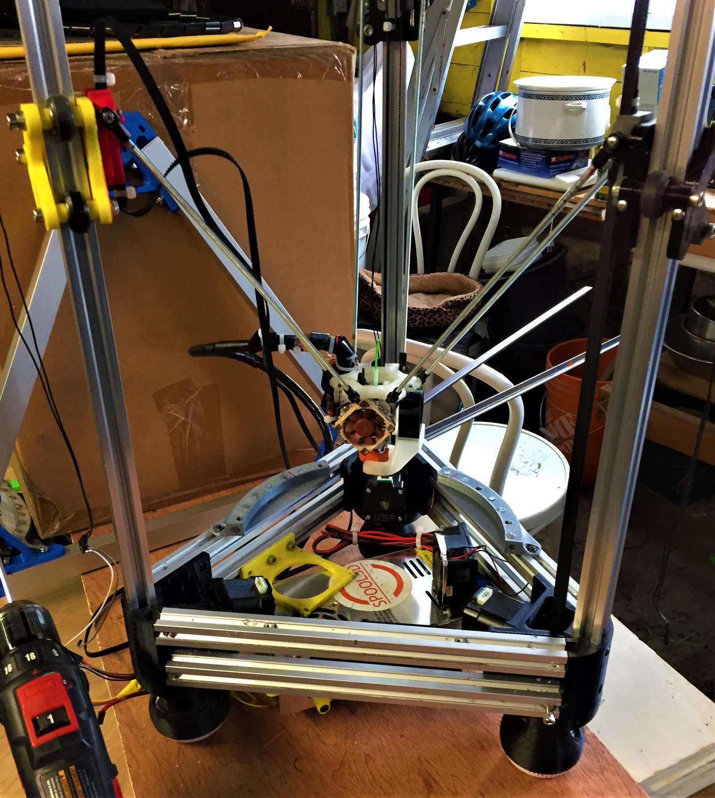
Completed install before testing

Monday, 19 October 2020

Ender 3 Upgrade: Dual Extrusion with SKR 1.3

Endurance ready to print
      Time for the reveal of a long-term project that's been around in various forms for a couple years, Duel-extrusion. Back in Febuary I'd started to experiment with converting my Ender 3 to dual-colour extrusion using a spare Lite6 hot-end and V6 clone that I found on Amazon.

Thing:3516409 mount
     Mounting the hot-ends for initial testing of the idea was fairly simple, there's lots of good mounts for V6 series hot-ends on Thingiverse, I specifically went with thing:3516409 to start with since it allows for reconfiguring from single to dual extrusion with only a couple printed parts as mounts. The next issue to tackle was electronics.

Ramps stack on Ender 3
     Now, the Ender 3 default electronics are fairly good for a basic single extrusion printer, but don't allow for duel nozzles, so I swapped the silent 1.1.4 board from my last upgrade out for a spare Ramps/Mega2560 stack that I normally use on my MPCNC. The Mega2560 isn't rated for 24V power but there is a fairly old work-around that solves this problem on the RepRap wiki, I then wired a spare LM2596 buck converter to provide the needed 12V power for the processor board's onboard regulator and the hardware side was ready for inital testing.

BigTreeTech SKR 1.3 with stepper drivers partially installed
    Unfortunately, this was right at the start of April 2020, so testing things out got put on hold until June since all of my printers were fabricating PPE gear as part of BCC3D.ca's efforts. This showed that Ramps at 24V is ok for short-term use, but I had one of my extruder stepper drivers blow out, so a better solution was needed for long-term usage. Some research on newer 32-bit boards showed that the BigTreeTech SKR 1.3 board fit the needs of this upgrade perfectly.

Custom dual hot-end mounts
    The other short-coming that was revealed was the dificulty in aligning the duel hot-ends correctly since this type of dual-extrusion setup needs the nozzles in the exact same horizontal plane or close enough to make no difference with the intended layer-height. The Thingiverse mount had both hot-ends locked at the same height at the top but not at the bottom, so I pulled a copy of the Ender 3 source-file into Fusion 360 and started drawing up a custom mount pair to fix the issue. 

Design in progress
     My solution to the problem has the right-hand hot-end at a fixed height bolted to the stock hot-end mount posts since that's the zero reference point for the entire printer coordinate system. The left hot-end is tucked into a dead-space on the side of the tool-plate that's normally used for mounting optional auto-levelling probes but is the exact right size to fit a V6 heat-sink while allowing both nozzles to reach the full width of the bed. With all that sorted out it was finally time to calibrate and try this out.

First Duel-extrusion print straight off the bed
     Now, obviously there's a fair bit of slicer tinkering needed to get a custom duel-extrusion system setup, so I loaded a couple lengths of scrap filament into the extruders and printed several test objects (thing:2388496, dual block object) to get the horizontal offsets correct in the firmware, then created a custom version of the Ender 3 profile in Prusa Slicer v22 with some custom startup gcode to get things heated correctly. Other than that I just turned the 'ooze shield' settings on, drew up a simple vase as a test part and turned it loose.

First dual-colour print after inital cleanup
     Clearly things aren't perfect, still some tuning with the retraction settings given the blobs all over the surface, but I'm quite pleased with how it turned out for a first print after all the work that's gone into this upgrade. The SKR board has proven quite robust and reliable, been running it non-stop for about 4-months now without issue so they're now my first choice for new printer controllers going forward.

Sunday, 1 March 2020

Yearly Overhaul: Mega Kossel

Mega Kossel
       One year after building the Mega 2.0, some of the reused components started to wear out and cause issues, so this is an overview of what's been updated and replaced over the past couple of months, primarily the print-bed and its related wiring along with some worn out cables in a couple areas.

Mini Kossel Power Switch after overload surge
     The first issue that came up was the original power switch overheated and partially melted due to an improperly matched circuit breaker from an old refit allowing sustained over-current during the heat-up cycle at the start of a print, I think that's what happened anyway. Fortunately the fix was very simple, one of these IEC Socket with Switch and Fuse Holder units and a 5A glass fuse from the local electronics store, and some wire from an inexpensive extension cord covered the electrical side. Mounting the new plug was mostly a matter of designing a custom bracket for it to sit in and bolting that to the underside of the frame, then connecting everything to the power supply and that issue was fixed.


New power socket wired up and ready for mounting shell
Power Socket installed in printed housing for safety


      With the power input repaired, the second and more critical issue that came up was a mechanical failure of the original heat-bed power input cable where it was soldered to the Kapton heater disk. Re-soldering it worked temporarily but it broke a second time in the exact same spot and the second break ripped a hole in the copper layer of the circuitry, so it was time to retire the old thing and get a more solid MK3 bed variant to do the job.

New heat-bed stack components, from left to right:
spare aluminum, cotton insulation, 300mm MK3 bed, and Creality magnet kit
     Parts used in the new bed are basically the larger versions of the ones installed on the Sculptor and Ender 3. A 300mm MK3 aluminum bed is the electrical and structural core, with a sheet of cotton insulation to protect the electronics bay taped on the back. Upper surface is coated with the magnet sheet out of a Creality magnetic bed kit to mount the existing spring-steel sheet bed surface. I'm not using the Creality upper surface since they have a tendency to crack and breakdown after a fairly short usage lifetime.

New bed supports installed on Mega
     Of course, the change in bed shape means that a new set of bed supports are needed, some quick CAD work with the design files had the relevant parts drawn out and sent off to the Ender 3 and Sculptor for fabrication. Once that was done and bolted down, it was time to solder the electrical cables onto the new bed since it didn't come with the wires pre-installed, so here's some soldering in low-temperatures 101.

MK3 bed positioned on Ender 3 print surface for easy soldering.
     It was freezing cold out when this refit was done, workshop was just under 5°C average temperature, so the solder wasn't heating up correctly on the workbench or iron. Seems that solder needs about 20°C to work correctly, so I flipped the bed I was working on upside-down on my Ender 3's build-plate after cranking it up to 60°C. This managed to transmit enough heat into the parts being worked on to get things flowing correctly and it was fairly simple to finish installing after that.

Tuesday, 14 January 2020

Upgrading the Sculptor: Bondtech BMG gearing, Silent fans, and Thermistor replacement

Sculptor ready to print
    Time for some 3D printer upgrades! This time it's the Sculptor i3MK2.3 under revision, specifically the print-head assembly. After refitting my Ender 3 with Bondtech gears during the early fall. I was quite impressed with how reliable they after a couple hundred hours of printing. So when a decent quality clone of the BMG turned up on Amazon, it was time for a much needed upgrade and overhaul for my second oldest printer.

E3D Thermistor and Capricorn XS PTFE tubing.
New (top) and old (bottom) E3D thermistors
   First step of the upgrade process was to strip down the existing tool-head and check the electrical parts for any issues that may have come up over the last year or two of use. One issue that I'd been aware of going into this refit was a bad bearing in the hot-end fan, but as soon as I removed the part fan it became clear that there was a major safety issue with the thermistor cartridge, specifically that part of the insulation had frayed away from the wires it was supposed to protect, that could cause a fire if the control board glitched at the same time, so getting a replacement became the top priority for this upgrade cycle. Fortunately it turns out that E3D had already fixed the manufacturing fault that caused the issue, so I ordered a couple of the updated version, one as a replacement and one spare for future repairs.

Secondary extruder gear installed on idler arm
    Bondtech actually has a specific kit of the BMG that is meant for refitting an i3MK2, so there are SLS optimized source files to work from for the printed parts, fortunately I found an FDM optimized remix on Thingiverse (thing:3347150), so it was just loading the parts into a batch on one of the other printers, cleaning off supports and starting assembly using the online instructions from the official kit as a guide on what goes where.

Gearing system half installed on motor
Assembled Tool-head bolted onto gantry
    Once the mechanical assembly was done, it was time to sort out the electrical issues that had cropped up. Since I had the tool-head apart anyway, the hot-end got stripped down to components and refitted with new parts, Capricorn XS PTFE for the barrel lining, a fresh nozzle and the replacement thermistor, all fairly simple refits but you do have to dismantle the lite6 hot-end to do them. With that side of things done, it was time to deal with the worn out fan.

Fractal Designs Silent Series R3 4010 12V fan
     My local computer store turned out to have some nice 4010 fans from Fractal Designs in stock, so I picked one up to test it out and see how it compared to the Noctua model on the Mega Kossel. Visually, they're quite different, the Noctua has a smaller core with larger blades whereas the Fractal looks more standard, but sound-wise they're about the same when powered up, so I'm fairly happy with the Fractal Designs model and I'll probably be using them in future refits.


Fractal Designs fan installed and ready
     Once all the fans were mounted, it was time to calibrate the extruder and do a test print. Instead of the usual 3DBenchy, I decided to try the Lattice Cube by Lazerlord (thing:1850320) and see how it turned out. 6 hours of overnight printing later, I was greeted by a nearly perfect print when I came into the workshop to check on it. Overall I'm expecting this upgrade to keep the Sculptor running reliably for several years to come.


Lattice Cube freshly printed

Wednesday, 26 June 2019

Part Review: TMC2208 Stepper Drivers

MKS TMC2208 Stepper Driver
      During a recent maintenance session on the Mega Kossel, I installed some TMC2208 stepper drivers into the X/Y/Z sockets to replace the original drivers. Below is a short guide on how to install them on a printer board, along with my impressions after a month of use on a primary production printer.

Ramps 1.4 with TMC2208 drivers on main motion axis
    As you can see from the above picture, these drivers are meant as drop-in replacements for the popular A4988-series that the majority of 3D printers use by default, so upgrading to them works mostly the same way on any control board with plug-in drivers. The key to getting them socketed properly is to line up the pin marked 'EN' or 'Enable' with the same corner of the board socket, it's usually marked on the board, but for the Ramps-series it's the corner pin closest to the power input, centre top in the picture above. The other main change needed is to pull the third jumper in the step selector, make sure to do this before installing the driver since that pin is different between the A4988 and TMC2208 pin-outs.


    The most noticeable difference upon starting a print is just how quiet the printer is, there's barely any sound other than the actual belts moving and the cooling fans, quiet a difference from the A4988 drivers. They also have some nice effects on print quality, prints made before the upgrade had a slight ripple effect that was from minor vibrations shaking the nozzle slightly, those have been vastly reduced with the TMC2208 drivers installed.

3DBenchy post installation,
     This is the #3DBency being printed in the video clip, as you can see the ripple pattern is still present but vastly reduced, so I'm quite happy with the end result of the upgrade, minor stringing aside, I'll probably update my other printers with them eventually as well. In conclusion, are TMC/Trinamic drivers worth it? Yes if you want to make the printer drastically quieter without redoing the motor mounts or are looking to maximize print quality. 

Monday, 25 March 2019

Beefing up a 3D printer: Mega Kossel 2.0

Mega Kossel, January 2019
     After installing the Titan Aero on the Mega Kossel in January, I started to notice some twisting induced artifacts in the prints. Investigating them lead me back to the old corner brackets that were starting to show signs of cracking and fractures after almost 4 years of nearly non-stop usage, so I decided it was time to replace them. I was playing around with some numbers on an old copy of the Kossel frame calculator spreadsheet and found that my current rod-arms were long enough to use with the 300mm heat-bed that I'd originally bought for the Proteus, so I set about locating the materials for a refit/rebuild.


Mega Kossel 2.0 Corner brackets
     After finding that the local hardware store stocked 25mm (1 inch) aluminum square tubing, I decided to implement a trick that I'd seen online of having 3 towers on the corners of the frame instead of 1 to reduce or eliminate twisting issues, so I reworked the corner brackets to allow for external towers with auxiliary hard-points. The Mega was still functioning fairly well so I had it print off the replacements prior to dismantling it for rebuild.

Mega Kossel partially dismantled
     Since I was going to be replacing the print-bed with a larger model, I basically ended up pulling the electrical harness, v-slot towers and effector assembly off the old form of the Mega and scrapping the old triangles for parts. Once the green braces that were holding the towers in at the bottom were removed, the towers started flexing by almost 5 degrees over the frame height, one of the upper triangle brackets even shattered during removal, so clearly the frame was overdue for a full refit.

Mega Kossel 2.0 Upper Triangle

Mega Kossel 2.0 Lower Triangle under construction

     Assembling the upper and lower triangles was fairly simple from a structural perspective, but not so much from the electrical side of things. The 300mm heat-bed uses a 24V heater and the entire electrical harness was previously 12V, so I did some research into dual power systems and ultimately took a page out of DC42's Delta Build, specifically using an SSR relay to isolate the 12V and 24V power feeds. I had a spare 60W 12V power brick floating around from when I upgraded the Sculptor with a heated bed last fall, so I put it to use to power the motors, hot-end and control board on the new Mega 2.0 setup.

12V and 24V power supplies partially installed
    Having doubled up power supplies in the lower triangle does impose a certain amount of space restrictions, so I ended up spreading the control boards around the edges after sticking the power supplies in the centre. The Ramps/Re-ARM stack is mounted to a customized version of the 2020 bracket with the OctoPi module stuck on the opposite side, the SSR and voltage converter are mounted where there was space to fit them past the bundled wire leads. Not the neatest layout, but it gets the job done.

Lower Triangle structure completed
Installing the SSR and bed power lines
    Assembling the outer frame braces was a bit interesting, I made a couple minor errors that resulted in there being nearly zero clearance between the carriages on the motion towers and the structural brace towers beside them, resulting in binding issues the first time I tightened one corner down fully. The solution was fairly simple, I just loosened the tower that was binding slightly, slipped some sandpaper into the gap, the slowly tightened the tower back up while rubbing the carriage on the sandpaper. The resulting gap was more than enough to get the carriages running freely and reliably.

Mega Kossel 2/3 completed
    Once the last tower was fully mounted, it was just left to run the electronics through motion tests to ensure that everything was connected to the proper interface. I did catch a rather funny issue that would have made everything print mirrored in one axis but that was the worst of the issues, so I promptly put it to full use on a couple of minor projects to test the quality of the prints before putting it to work.

Mega Kossel 2.0 Completed