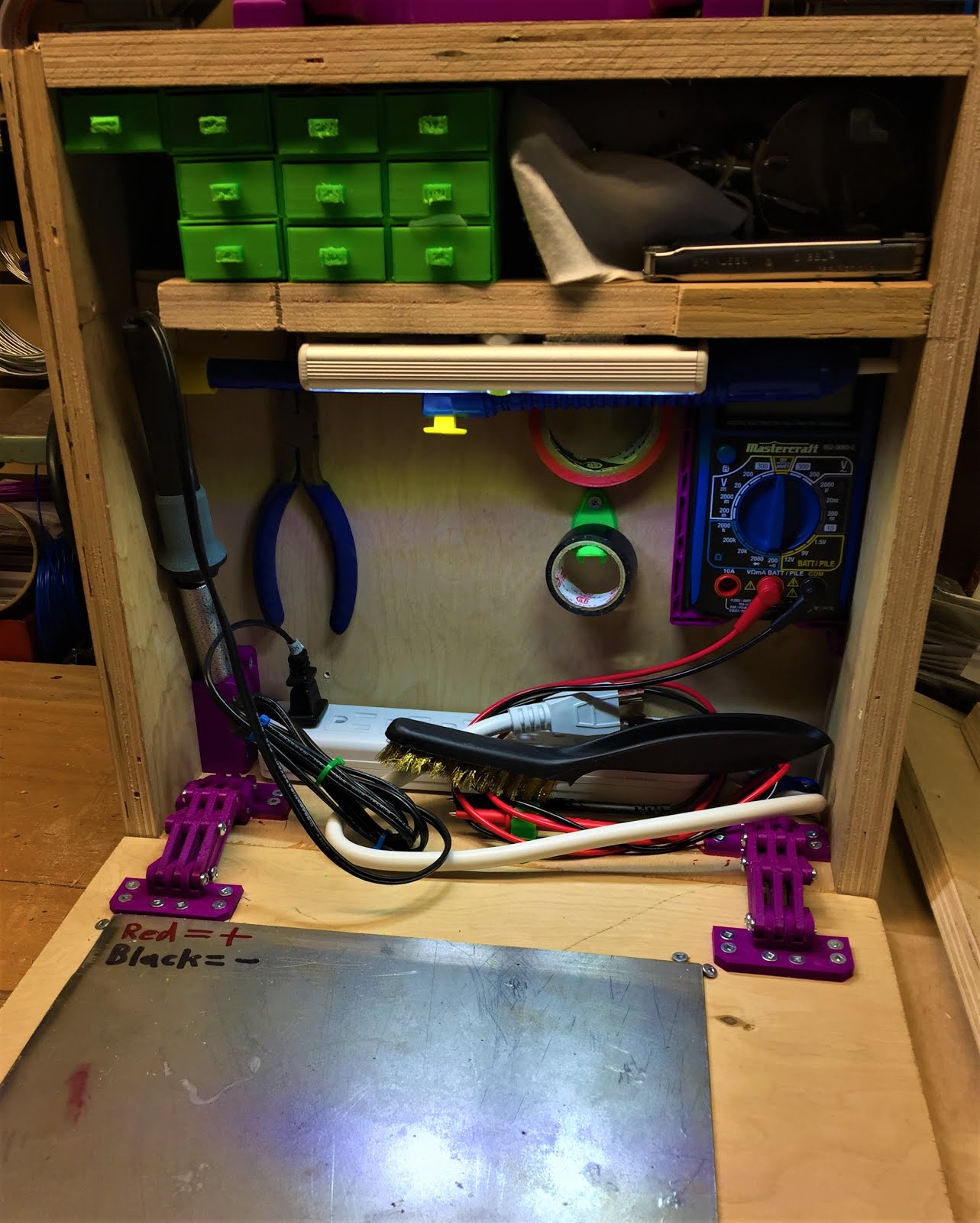
After doing a bunch of Electronics work on a recent project and having to chase my tools for such work though four or five toolboxes, I thought it was time to build something dedicated for such projects. After doing some research, I found inspiration in this 'Portable Electronics Workstaion' over on Instructibles, in particular the fold-down lid/worktop, so that got integrated with the design.
Initial tool layout inside the box
Constructing the actual box was fairly straightforward, it's just some leftover birch plywood that was in the woodrack, cut to size and screwed together with some 2 inch 'deck screws', nothing fancy but it's very sturdy and I can dismantle it with a screwdriver if I ever want to change something. The hinges are thing:2401035, and the latches are thing:2425378, both fairly nice designs that work quite well with the handle being custom work of my own. I'm using one of the leftover steel plates from the Mega Kossel's old form as a working surface, flipped over the back is plain steel, plenty sturdy enough to handle a stray iron or other hot tool, I've just used some spare screws in pairs at the corners to clamp it to the inside of the lid for easy storage.
Second iteration of interior layout
As for what's in the box, I've got my larger multimeter in the right-hand corner, then some hooks for electrical tape (thing:2900008), my soldering iron in a custom stand on the left, power-bar to control the iron along the bottom, and some needle-nose pliers and a multi-tool on the back wall. Just below the shelf is my de-soldering pump and an LED 'work-light' type flashlight, then some custom drawers on half of the shelf above. The drawers are filled with small consumables like heat-shrink tubing and solder, stuff that gets used all the time in small amounts during projects.
Fume extractor parts
On the safety side, I've got a cheap filter mask just above the iron, along with a custom built fume extractor on the upper shelf. Parts wise, the fume extractor is a 6025 12V fan that was leftover from the airfiltered enclosure build, along with a section of a commercial fume extractor filter cut down to fit. I created a custom enclosure in Fusion360 to fit the fan, then printed the parts out and bolted things together.
Fume extractor with fan installed, filter waiting for installation
Power is fairly simple, I've got an adapter for the batteries for my power drill that takes a 2.5mm barrel jack, so I just fitted a spare plug to the fan's power leads, simple and easy to maintain. The actual filter is activated carbon with a custom holder, it's secured with some M3 bolts for ease of replacement whenever needed.
Completed Fume extractor ready for use
Overall, I'm happy with how this workstation/toolbox turned out, it should make any future soldering and electronics projects much easier and safer going forward.
During a recent maintenance session on the Mega Kossel, I installed some TMC2208 stepper drivers into the X/Y/Z sockets to replace the original drivers. Below is a short guide on how to install them on a printer board, along with my impressions after a month of use on a primary production printer.
Ramps 1.4 with TMC2208 drivers on main motion axis
As you can see from the above picture, these drivers are meant as drop-in replacements for the popular A4988-series that the majority of 3D printers use by default, so upgrading to them works mostly the same way on any control board with plug-in drivers. The key to getting them socketed properly is to line up the pin marked 'EN' or 'Enable' with the same corner of the board socket, it's usually marked on the board, but for the Ramps-series it's the corner pin closest to the power input, centre top in the picture above. The other main change needed is to pull the third jumper in the step selector, make sure to do this before installing the driver since that pin is different between the A4988 and TMC2208 pin-outs.
The most noticeable difference upon starting a print is just how quiet the printer is, there's barely any sound other than the actual belts moving and the cooling fans, quiet a difference from the A4988 drivers. They also have some nice effects on print quality, prints made before the upgrade had a slight ripple effect that was from minor vibrations shaking the nozzle slightly, those have been vastly reduced with the TMC2208 drivers installed.
3DBenchy post installation,
This is the #3DBency being printed in the video clip, as you can see the ripple pattern is still present but vastly reduced, so I'm quite happy with the end result of the upgrade, minor stringing aside, I'll probably update my other printers with them eventually as well. In conclusion, are TMC/Trinamic drivers worth it? Yes if you want to make the printer drastically quieter without redoing the motor mounts or are looking to maximize print quality.
Over the Christmas season my family discovered some of The Piano Guys music videos and I remembered coming across the O'Cello & Mina Violin files, so I got some transparent PLA and started printing the parts. The designers intended for the parts of both projects to be printed on a standard i3-type printer, but I ended up using the Mega Kossel instead.
Mina Violin neck freshly printed
Printing the Mina Violin body on the Mega Kossel
As you can see, printing some of the parts needed some creative positioning of the parts, the lower body of the violin was particularly tricky, I ended up standing it on end, rotated by 30° onto one side and tilted back by 10° to get it to fit. After printing, some cleanup was needed, mostly stripping support material and stringing off, but on the violin the fingerboard came out a bit rough, so I sanded it down smooth then removed the heat induced scarring, as sanding PLA tends to mess up the finish.
Sanded PLA fidget cube
The solution to the scarring issue is to take a heat-gun and run it lightly over the surface, don't pause in one place or you'll melt the print, and after a few passes the colour will reset and be indistinguishable from a freshly printed surface in colour. I'm using a light-duty 'art & craft' gun, but for the more industrial models you'll want to stick to the low setting, the higher one's will just wreck the print.
Heat-gun from Opus Art Supplies
Heat-treating before (bottom of cube) and after (top of cube)
Finished cube, note the distortion on the thin sections from overheating
With the printing finished, the next step was sourcing the non-printed parts, I ended up using these piezo pickups from Amazon.ca instead of the default ones on both the violin and cello because the original ones are only available on Amazon.com and don't ship to Canada. The tuning pegs were these ones for the violin, and these for the cello. The strings are D'Addario Prelude for the cello and Thomastik Dominant for the violin, both bough from the local music store. All the fasteners were easily found at the local hardware store along with the structural threaded rods, 5/16" for the Violin and 7/16" for the Cello.
Mostly assembled O'Cello
Stringed O'Cello with Viola bow for scale
After all that, the actual assembly was fairly straightforward, and they both sound surprisingly good, the O'Cello actually producing a decent level of sound even without the amplifier. The Mina violin turned out to produce a decent level of sound when played with a viola bow, I'm guessing the extra weight compared to a violin bow helps produce more volume of sound? Regardless I'm happy with how both turned out.
I just finished a partial refit on my Mini Kossel, and realized that I hadn't mentioned it on here yet, so here's a brief tour of the upgrades and modifications from this past year. Most of the important ones I've made are related to the plastic handling components, so I'll cover them by following the filament path.
Starting from the top of the filament path, the first modification I added was this spool holder by Creative Tools, specifically the OpenScad remix done by GeoDave on Thingiverse. This is by far the nicest spool holder I've used to date, most of the other ones for deltas ether occupy the upper triangle completely or are just a printable stick that bolts onto the side, so this is a massive improvement over those options.
Greg's Wade's Extruder, bowden variant
After the Mini Kossel's previous MK8 extruder suffered a dulled drive gear recently, I decided to replace it with a Greg's Wade's extruder, an old and proven design from the RepRap project. I've had it running for about two weeks at this point, and it's been very solid and reliable.
E3D Lite6 nozzle
Next on our tour is one of the first upgrades I made, the E3D Lite6 hot-end. The Mini Kossel kit came with a 'metal J-head' hot-end that malfunctioned the first time I turned it on, and started oozing plastic out of every joint in the heater block, regardless of what I tried. After researching hot-ends online, the Lite6 quickly came up as a reliable and easy to use option for a beginner, and I've not looked back since.
MK3 aluminum heat-bed with Buildtak on glass topper
Finally, we come to the heated build-plate or print-bed, the foundation that everything is printed on. I started out with a MK2a PCB heater and glass combination that was included in the kit, but the heater was warped when I got it, so I sourced a MK3 aluminum heater as a replacement and I haven't had any issues with it since. The Buildtak print surface is something I started using on the Micro a few months ago, and I decided to add a sheet to one side of my glass bed after I ran out of the glue stick that previously served to improve bed adhesion. And that's my workhorse printer's key upgrades finished, for now.
Or Building a large Delta from Electrical Conduit part 1:
A couple of weeks ago, I backed DisTech Automation's Prometheus System on Kickstarter, and decided that rather than refit one of my existing printers, I'd build a new larger delta specifically for it. After building the Micro Kossel and MPCNC, I ran across the incomplete Emmett-Delta on OpenBuilds, which had some interesting ideas for using electrical conduit for the frame, rather than the usual expensive V-slot. I decided to go with a 30cm diameter build plate with 1 meter of build height, so the overall size is about 1.5 meters tall with a 50 cm per side base, making this something of a monster-sized machine.
Emmett-Delta parts waiting for assembly
For the frame, I'm using 60 feet of 1/2 inch electrical conduit for the towers, and about 12 feet of 3/4 inch electrical conduit for the top and bottom triangles, you can see some of the 3/4 inch pieces in picture with the printed parts. On the 3D printed parts, I got in touch with the original designer, David Bunch, and he finished designing some of the missing parts so I could do a full build. For the controller, I'm using the well reviewed Duet 0.8.5 and pairing it with a 24 volt heat-bed from UltiBots, I'll have more on those in a future post.
Side bar fitted with drilling jigs
Preparing to drill with 3/16 inch bit
For filament usage, I've gone through just over 1.5 kg so far, half of that in the lower corner brackets that clock in at 240 grams each. Once I'd finished printing the corners, cutting and drilling the electrical conduit to it's final size was next. Cutting was fairly straight forward, since I used this technique with a reciprocating saw, metal blade, and miter box. As for drilling the holes to actually bolt things together, I tried doing it by hand with a power drill and 3 days later, ended up with my holes all over the place. If I did it again, I'd invest in a drill press for faster and more accurate drilling.
Side bars waiting for installation. Note the messy holes from hand drilling
The primary assembly tools: a ball-ended hex key, and a 6" crescent wrench
Once I got the screw holes straightened out, the actual assembly for the triangles is fairly straightforward, line up the holes, insert a bolt, loosely thread a nylock nut onto bolt, repeat at next hole. I did this until all of the sides for each triangle were loosely assembled, then went around the sides tightening each bolt in turn until all of them were snug, then gave each a tiny bit more of a twist to completely lock the frame.
Top triangle fully assembled
First side of lower triangle assembled, note the installation of the bed support bracket
When assembling the lower triangle, it quickly became apparent that I'd need to install the brackets for the electronics and print bed during the assembly, otherwise I'd need to remove the upper bars to install them and potentially damage the alignment on one or more of the sides.
Lower Triangle fully assembled, including brackets for controller board
Brackets for Duet 0.8.5 controller with space for optional Duex4 expansion board
Once all of the bolts were tightened, it was time to start work on assembling the towers, which I'll cover next time.
Over the past month or so, I've been building a new tool, a 3D printed CNC router table. It's called a Mostly Printed CNC, designed by Ryan Zellars, and is capable of working as both a router table, 3D printer, laser engraver or just about any other device with similar motion mechanics.
Mostly Printed CNC waiting for RAMPs installation
Building wise this is a fairly straightforward project, the main tools needed are a 3D printer with a minimum 170*170*170mm or 6*6*6 inch cube build volume, a hacksaw or reciprocating saw, a pair of 3 inch or bigger clamps, a miter box, a 5/16" or 8mm wrench and ratchet socket, phillips screwdriver, needle nosed pliers, a 2.5mm allen key and a decent set of digital calipers. Materials include 2 kg of PLA filament in whatever colours you like, 24 feet of 3/4" steel electrical conduit that I'd suggest getting first since it affects which of the 3 variations you print, about 20 feet of 4-strand electrical wire, 55 608zz bearings, a RAMPs 1.4 kit, a sturdy and flat-topped table or bench, and about 100 different bolts and screws (See the parts page on Ryan's blog for exact part counts).
For the 3D printing part of the project you'll first need to measure the outside diameter of the electrical conduit and download the appropriate variation of the parts from Thingiverse (23.5 mm North American version, 25mm international version, 25.4mm (1 inch conduit) version for extra strength/heavy use). Once you've downloaded the correct parts set, it takes about 90-100 hours of printing create all of the parts. I'd recommend keeping a close eye on how much filament is on the spool before starting some of the parts, particularly the 2 large 'Center XY' ones in the center assembly, they take 8.5 hours each and about 200 grams of filament, not something you want to hit the end of a spool on.
Center XY bracket undergoing bearing installation
Assembly of the parts is quite well documented on Ryan's blog, only section that I'd recommend doing differently is the center assembly since the 5 inch bolt is a bit of a pain to line up correctly if you're adding parts from top to bottom. I found it's much easier to combine the outer 4 parts and then add the 5 inch bolt and brackets for the z-axis threaded rod.
Center assembly parts with dremel spindle in background
Recommended method for assembling center block
The other main tricks and gotchas to be aware of are that the roller design was updated around the middle of july, main difference is that the top clamp and motor mount have been combined into one part, otherwise assembly is more or less the same. I'd also recommend glueing the leg caps to the bottom of the corner assemblies, otherwise it's a potential shearing point and could fail unexpectedly if unglued.
Updated roller carriages with bearings and belt guides installed
Applying 5-minute epoxy to corner bracket base for strength
Corner base and leg cap glued and clamped
Once the corner brackets are glued and all of the bearings installed, you'll need a large level surface to assemble and square the frame on. I found it's useful to have a building square to check the corners with, that and measuring the diagonals with a tape measure (if both diagonals are the same lengths, then the frame is square, if not the same use the square to check the corners and correct the issue).
Me assembling the main frame, note the installation of the roller carriages
Securing frame to 3/4 inch plywood for squaring
Installing motors and securing motion axis with wiring harness in foreground
As for the electrical install, I'd recommend referring to Ryan's Ramps and Stepper wiring guides if you're using the Ramps 1.4 board set, otherwise I'd suggest referring to the official documentation for whatever control board you decide to use. After testing that everything is wired correctly, I'd recommend installing one of the pen adaptors and testing the motion mechanics for any errors.
Ramps installed and pen tool mounted for initial testing
For a carving spindle a DeWalt 660 laminate trimmer/drywall saw is the recommended option, but just about any rotary tool, palm router, or laminate trimmer will work with some variable limits on speed and maximum material hardness. I'm currently using an old Dremel 250 rotary tool that's been gathering dust in the shop for a few years, and it's proven perfect for delicate detailed surface engravings with softwood (old pine mainly) and probably most other kinds of wood with the right tooltip. I'm eventually planning to upgrade to a Makita compact router (model number RT0701C) since it's the cheapest option I've found with a full speed control and stabilizer option. Here's a short video of the machine in action.
First engraving test result
Engraving with 1/32 inch ball tip engraver
Overall, this machine was a lot of fun to build and I'm looking forward to learning more about CNC work with it. One thing that I did change was to modify the stock firmware (Marlin from Ryan's blog) and disable all of the thermistor inputs since I'm only planning to use this machine as a CNC for the foreseeable future.
For the past 2 weeks I've had a side project going and now it's ready to share. I call it Project: Vein Finder.
Project: Vein Finder powered and ready
If you're wondering what a vein finder is, it's a specialized flashlight used by medical professionals to locate veins under the skin when starting i.v. lines or giving injections.
Vein Finder prototype ready for testing
Basic operation is fairly simple, flip the switch to turn it on and hold it about 6 inch above the section of skin you're searching for veins, the red light acts as a highlighter for veins and makes it easier to see them.
Vein Finder Parts with LEDs installed
The parts list is fairly simple, 6 620-680 nanometer 5-6000 millicandela LEDs, 6 51 Ohm 1/4 watt resistors, a 2 position switch (SPST Rocker in this case), a holder for 2 'AA' batteries, 2 'AA' 1.5 volt batteries, and some dark colour 3D printer filament.
Electronics installed and ready for initial testing
Tools needed are a 3D printer, a decent multi-meter, needle nose pliers, wirestripers, and elecrical tape to insulate the internal connections. The internal circuit is fairly simple, just connect the positive lead from the battery holder to the switch, switch to the positive leads of the LEDs in parallel, negative leads of the LEDs to a 51 Ohm resistor independently, and finally connect the resistors to the negative lead of the battery holder.
Vein Finder with cover for forward electronics installed