Showing posts with label Tips and Tricks. Show all posts

Sunday, 2 May 2021

Remote Power Control Update

Remote Power Setup from last time
     There's been some changes to the remote power setup from last post, so I've documented the updates here if anyone wants to duplicate this modification. It's primarily a hardware change but there has also been a software update to the OctoPi plugin that can be a bit confusing for new users.

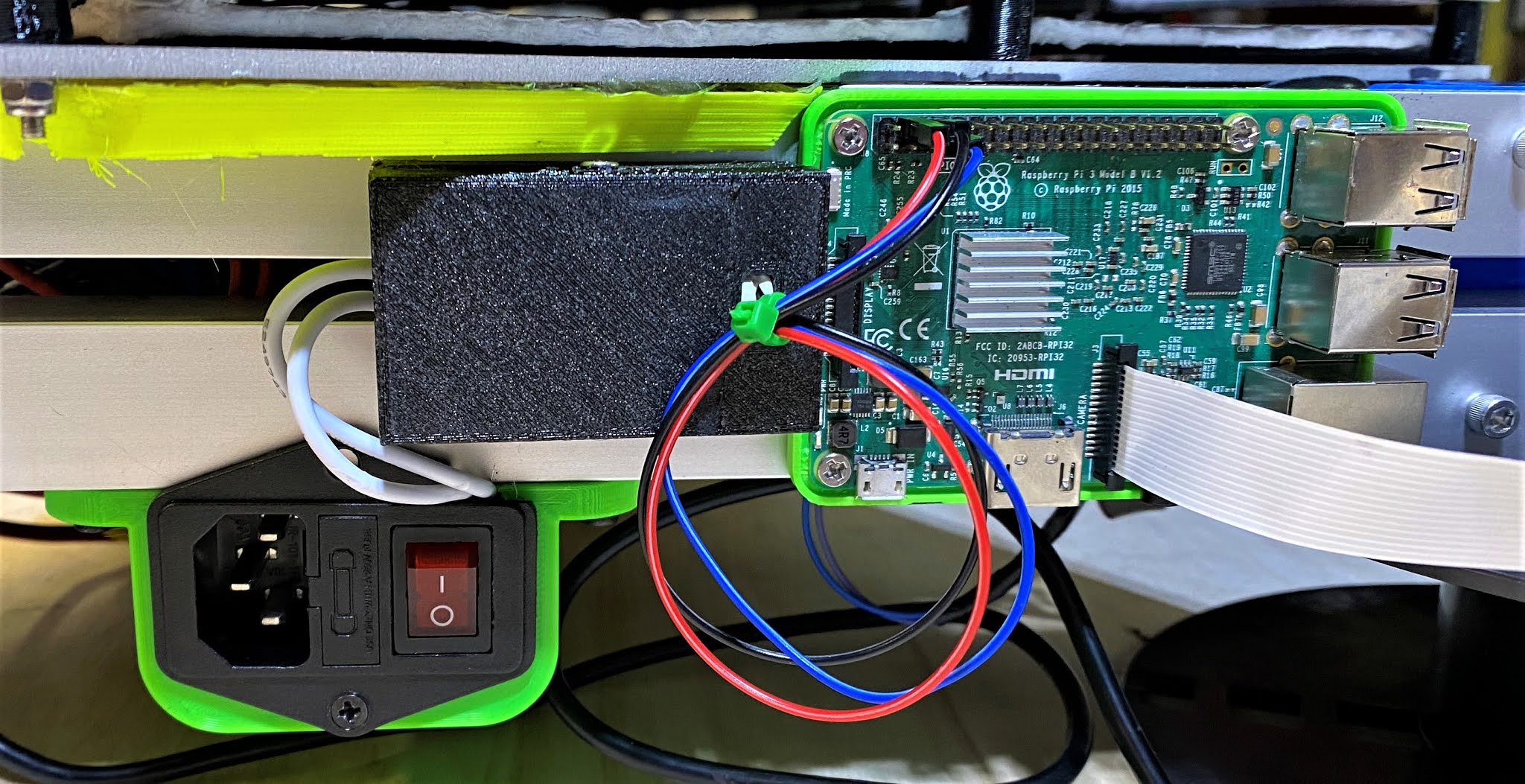
     The hardware side has changed over to a proper Raspberry Pi Hat, mainly due to the relay from last-time glitching out once the temperature in the workshop went from 10°C average to around 20°C, something about that slight increase made the relay trigger current increase past the Pi's current output limits. This isn't covered in the data sheet for the 'JQC-3FF-S-Z' relay that I've been able to find, so your results with that relay may vary depending on the environment the printer lives in. I've upgraded to the Keyestudio 4 Channel Relay Hat which uses relays that actually play nice with the Pi's onboard current limits, installing it was almost plug-in and go, only needing to screw the load lines into the terminal blocks to finish hardware installation.

Updated Settings for PSU Control

     On the software side, the creator of the 'PSU Control' plug-in did a major overhaul of the code-base in April, end result was it splitting into 3 plug-ins. The original which is now basically the switching logic for when to turn things on/off. And a pair of support plugins that act as interfaces for Raspberry Pi GPIO or TPlink smart plugs so far. Functionally this means that the 'Switching' settings need to be set to 'Plugin', and then the 'PSU Control RPi.GPIO' plugin installed via the plugin manager.

PSU Control RPi.GPIO settings

    Configuring the new plugin is fairly simple, it's really just a matter of telling what pin-mapping mode and which pin is in use for the printer relay. I'm using what the plugin calls 'BCM' mode, identifying the pins by the logic name instead of the more common 'Board' mode since it seems to be slightly more reliable. For the hat I'm using, the relays are on BCM pins 4, 6, 22, and 26. Setting up is just a matter of putting in the number for the relay in use, 4 in my case, and setting the logic to inverted since I've wired the printer as 'normally closed' and the plugin assumes the more common and generally safer 'normally open' logic by default. That concludes my follow up on this subject, next time its going to be looking modernizing an old relic from the early days of RepRap based printing.

Wednesday, 20 January 2021

Remote power control with Octoprint

10A relay module

     Over the last couple months I've been working on a bunch of secret stuff and workshop upgrades, more on those later in the year, but one project I can share is converting the Mega Kossel to full remote control via the attached Octoprint node. Out of the box Octoprint allows for the attached printer to be monitored via USB and an optional webcam, but there isn't any means of switching the printer on or off remotely, resulting in a lot of wasted electricity to maintain it in a state of 'ready to print'. The solution for this problem requires a bit of hardware modification along with installing an optional plugin for Octoprint called 'PSU Control'. I'm going to start with the suprisingly simple hardware addition first.

Tools and parts for remote power control upgrade

      The primary addition needed to control the power state of the 3D printer, (North America only), is a common 10A relay of the type found in a lot of hobby electronics kits, I'm using this one from Amazon, but there are lots of variations to chose from, it just needs to have 5V switching logic for compatibility with the Raspberry Pi. The rest of the tools and supplies are some 16/18 gauge wire, 3 DuPoint jumper lines, a couple female spade connectors, a wire-crimp/striper tool, and a couple screwdrivers, #0 and #1 Philips in my case. I've also printed a case for the specific relay module, but any electronics project enclosure will work, this is a key safety precaution since the relay will be switching mains power and the terminal block does have exposed metal on the top and front, so this modification is at your own risk.

Inside of power socket/switch with target wire removed.
     The first step is to unplug the printer and unscrew the power switch/socket assembly, this usually is just taking 2 screws out from the top and bottom holes. Once the socket is out, there are a bunch of wires that lead to the power supply, we want to remove the short section of wire that leads from the fuse to the power switch, this is going to be replaced with some leads to the relay. 
Relay polarity wiring
     Wiring the relay is fairly simple, we want it connected in the normally closed (NC) position. This allows the printer to still be used normally if the Octoprint node is offline for any reason. The other end of the 18-gauge wires should be crimped with the spade connectors, then one goes on each exposed blade in the power switch assembly.
Final Relay to Pi wiring
     On the OctoPi side, we're connecting to the 5V, 3.3V, GND, and one of the data pins on the Pi's GPIO, so you will need a 15W power block for the pi to prevent performance issues when the relay is active. Firstly I've pulled the coloured jumper and am using the relay board in isolated mode to prevent damage to the Pi's 3.3V logic systems. Full pinout is pin 2(5V) to JD_VCC, pin 1(3.3V) to VCC, pin 6(GND) to GND, and pin 13(GPIO) to IN1/Control. Of these, the only one you'll need to note down is which pin the control line is on. We'll need this number to configure the plugin in the next step.
Octoprint Settings with PSU Control installed
     Installing the PSU Control plugin is fairly standard for Octoprint, just searching 'PSU' in the plugin manager brings it up, after that it's just clicking 'install' and follow the prompts. Once the plugin is loaded, scroll down to the page shown above and switch the switching mode to 'GPIO', then enter '13' in the box below. After that scroll down to 'Power On Options' and enable 'Connect when powered on' with a 10 second delay and you're done for basic configuration. There's also a couple options to automatically shut-down the printer when idle or finished printing. These make it so the printer will stay completely dormant when not in use, ideal for when doing long prints that finish at odd hours.
Completed install before testing

Monday, 30 September 2019

Upgrading the Ender 3: Bond-tech gears, Bed Leveling Knobs and Part Fans

Ender 3 as currently configured
     After 6 months of using the Ender 3 in stock configuration I ran into a few areas that were showing signs of failing. So I thought I'd do a couple upgrades in the process of fixing them. Three key areas that were showing issues were the bed-springs, extruder idler arm, bed surface, and part-fan duct, so I picked out some upgrades for them.


1.75 mm Genuine BondTech drive gear kit.
    As the extruder is one of the highest wear parts on a 3D printer, any breakdown there is going to show up instantly in the printed parts. So I opted to upgrade to some BondTech drive gears with the original motor-end result is that I'm now able to print flexible filament without issue and haven't had a jam due to chewed up filament since. The housing is a PLA version of the official STL files from BondTech's website. They're surprisingly easy to print with an FDM machine-some slight supports in a couple minor areas and on the idler/compression arm and that was it.

Extruder Motor with BondTech mounting bracket
Fully assembled extruder block in use


   The next area that needed upgrading was my bed-levelling knobs. I came into the shop one morning to find one had spun clean off the bottom of the bed assembly from the vibrational force of normal operation. So I decided to install the same nyloc nuts solution that I've been using on my i3MK2 clone with some custom 3D printed replacement knobs.

Custom and Stock leveling knobs
New Leveling knobs fully installed, note M4 nyloc nut locking mounting screw
Flex-sure branded spring-steel build plate
    And speaking of the bed, I've been through a couple different printing substrates before settling on the current setup. I started with the official mag-bed upgrade after encountering bending issues with the strange flexible plate that came with the printer. The Creality mag-bed upgrade is much better than the starter plate, but the upper surface is far too rigid for practical use. Mine quickly developed cracks and started flaking apart with little bits stuck to prints. I was pleasantly surprised when a batch of spring steel plates that fit the Ender 3 build plate showed up on Amazon. It works perfectly with the magnet sheet from the official bed. I stuck some BuildTak on top and I've been using it ever since.

Radial part cooling fan (thing:3102082)
Electronics bay fan cover (thing: 3312856)
    And lastly are a couple upgrades from Thingiverse. First one is a 5015 radial part-cooling fan mount to replace the stock 4010 radial fan, (I've found that it gives about the same airflow with much lower noise levels, always a plus when working in the same space with the printer). The other upgrade is an elegant electronics bay intake cover, probably the simplest and most effective one I've found to date since it literally just snaps into place straight off the bed after printing. Combined, these two mods reduce the printer's noise level from a howl down to a minor background noise that is comfortable to work around.

Saturday, 31 August 2019

Workshop Upgrade: Electronics Workstation in a Box

Mystery Box
     After doing a bunch of Electronics work on a recent project and having to chase my tools for such work though four or five toolboxes, I thought it was time to build something dedicated for such projects. After doing some research, I found inspiration in this 'Portable Electronics Workstaion' over on Instructibles, in particular the fold-down lid/worktop, so that got integrated with the design.


Initial tool layout inside the box
    Constructing the actual box was fairly straightforward, it's just some leftover birch plywood that was in the woodrack, cut to size and screwed together with some 2 inch 'deck screws', nothing fancy but it's very sturdy and I can dismantle it with a screwdriver if I ever want to change something. The hinges are thing:2401035, and the latches are thing:2425378, both fairly nice designs that work quite well with the handle being custom work of my own. I'm using one of the leftover steel plates from the Mega Kossel's old form as a working surface, flipped over the back is plain steel, plenty sturdy enough to handle a stray iron or other hot tool, I've just used some spare screws in pairs at the corners to clamp it to the inside of the lid for easy storage.


Second iteration of interior layout
    As for what's in the box, I've got my larger multimeter in the right-hand corner, then some hooks for electrical tape (thing:2900008), my soldering iron in a custom stand on the left, power-bar to control the iron along the bottom, and some needle-nose pliers and a multi-tool on the back wall. Just below the shelf is my de-soldering pump and an LED 'work-light' type flashlight, then some custom drawers on half of the shelf above. The drawers are filled with small consumables like heat-shrink tubing and solder, stuff that gets used all the time in small amounts during projects.


Fume extractor parts
    On the safety side, I've got a cheap filter mask just above the iron, along with a custom built fume extractor on the upper shelf. Parts wise, the fume extractor is a 6025 12V fan that was leftover from the airfiltered enclosure build, along with a section of a commercial fume extractor filter cut down to fit. I created a custom enclosure in Fusion360 to fit the fan, then printed the parts out and bolted things together.


Fume extractor with fan installed, filter waiting for installation
    Power is fairly simple, I've got an adapter for the batteries for my power drill that takes a 2.5mm barrel jack, so I just fitted a spare plug to the fan's power leads, simple and easy to maintain. The actual filter is activated carbon with a custom holder, it's secured with some M3 bolts for ease of replacement whenever needed. 


Completed Fume extractor ready for use
     Overall, I'm happy with how this workstation/toolbox turned out, it should make any future soldering and electronics projects much easier and safer going forward.


Completed toolbox ready to use.

Monday, 25 March 2019

Beefing up a 3D printer: Mega Kossel 2.0

Mega Kossel, January 2019
     After installing the Titan Aero on the Mega Kossel in January, I started to notice some twisting induced artifacts in the prints. Investigating them lead me back to the old corner brackets that were starting to show signs of cracking and fractures after almost 4 years of nearly non-stop usage, so I decided it was time to replace them. I was playing around with some numbers on an old copy of the Kossel frame calculator spreadsheet and found that my current rod-arms were long enough to use with the 300mm heat-bed that I'd originally bought for the Proteus, so I set about locating the materials for a refit/rebuild.


Mega Kossel 2.0 Corner brackets
     After finding that the local hardware store stocked 25mm (1 inch) aluminum square tubing, I decided to implement a trick that I'd seen online of having 3 towers on the corners of the frame instead of 1 to reduce or eliminate twisting issues, so I reworked the corner brackets to allow for external towers with auxiliary hard-points. The Mega was still functioning fairly well so I had it print off the replacements prior to dismantling it for rebuild.

Mega Kossel partially dismantled
     Since I was going to be replacing the print-bed with a larger model, I basically ended up pulling the electrical harness, v-slot towers and effector assembly off the old form of the Mega and scrapping the old triangles for parts. Once the green braces that were holding the towers in at the bottom were removed, the towers started flexing by almost 5 degrees over the frame height, one of the upper triangle brackets even shattered during removal, so clearly the frame was overdue for a full refit.

Mega Kossel 2.0 Upper Triangle

Mega Kossel 2.0 Lower Triangle under construction

     Assembling the upper and lower triangles was fairly simple from a structural perspective, but not so much from the electrical side of things. The 300mm heat-bed uses a 24V heater and the entire electrical harness was previously 12V, so I did some research into dual power systems and ultimately took a page out of DC42's Delta Build, specifically using an SSR relay to isolate the 12V and 24V power feeds. I had a spare 60W 12V power brick floating around from when I upgraded the Sculptor with a heated bed last fall, so I put it to use to power the motors, hot-end and control board on the new Mega 2.0 setup.

12V and 24V power supplies partially installed
    Having doubled up power supplies in the lower triangle does impose a certain amount of space restrictions, so I ended up spreading the control boards around the edges after sticking the power supplies in the centre. The Ramps/Re-ARM stack is mounted to a customized version of the 2020 bracket with the OctoPi module stuck on the opposite side, the SSR and voltage converter are mounted where there was space to fit them past the bundled wire leads. Not the neatest layout, but it gets the job done.

Lower Triangle structure completed
Installing the SSR and bed power lines
    Assembling the outer frame braces was a bit interesting, I made a couple minor errors that resulted in there being nearly zero clearance between the carriages on the motion towers and the structural brace towers beside them, resulting in binding issues the first time I tightened one corner down fully. The solution was fairly simple, I just loosened the tower that was binding slightly, slipped some sandpaper into the gap, the slowly tightened the tower back up while rubbing the carriage on the sandpaper. The resulting gap was more than enough to get the carriages running freely and reliably.

Mega Kossel 2/3 completed
    Once the last tower was fully mounted, it was just left to run the electronics through motion tests to ensure that everything was connected to the proper interface. I did catch a rather funny issue that would have made everything print mirrored in one axis but that was the worst of the issues, so I promptly put it to full use on a couple of minor projects to test the quality of the prints before putting it to work.

Mega Kossel 2.0 Completed

Friday, 25 January 2019

3D Printer Kit review: Creality Ender 3

Mystery Box
     New year, new printer in the workshop. Over the 2018 holiday season, I purchased a Creality Ender 3, so this is my mini-review of what's in the box and my experience using it to date. On first getting the box, it comes with just the shipping label stuck to the outside of the printer's box, so it's clearly marked as to the contents, it weighs about 6 kg at a rough guess, so be ready for a large and heavy package.


Interior of shipping box with top foam removed
    Opening the box reveals that much of the interior is packed with this grey plastic 'foam', quiet dense and sturdy. Unpacking revealed that all parts were securely nested in fitted holes, wrapped in cling film for the extrusions, and in multiple bags for the smaller parts.


Gantry parts fresh out of the box

Ender 3 base and Power supply freshly unpacked

     The printer is about half built straight out of the box, all the electrical systems are pre-installed and it's mostly just a matter of following the instruction sheet that's at the top of the box to get it fully assembled. I would recommend plugging the included microSD card into a computer, there's an animated video clip on it that goes through the entire build process step by step, it helps clarify a couple of points in the printed instructions. I did make a couple minor changes to the printer during assembly, mostly optimizations that the user community has come up with over the past year or so. 


Part cooling fan ducts, stock on the left, thing:3079610 on the right
     Probably the single most crucial change I made was to replace the stock part-fan ducting with thing:3079610, a 360 printed duct that puts the air where it's needed and not into the side of the heater block like the original will. I've been down the road of part-fans blasting the heater block on the Sculptor i3MK3 variant ducting, once is quite enough for that issue. This silly piece of plastic is probably why early versions of the Ender 3 shipped with the firmware thermal watchdog disabled, a problem that's apparently been solved on the one I received since a cold snap a couple of days after assembly set off the 'Min-Temp' error code.


thing:3303879 installed backwards
thing:2934313 installed
     Other than the part duct, the other changes were mostly minor optimizations, a cover for the milled slot in the base that the electrical bundle runs through (thing:2934313), and one of the many side-mount adapters for the stock spool holder (thing:3303879). But aside from those, I assembled the printer as designed and set about testing it.


Assembled Ender 3 almost ready to print
     After a bit of research turned up that Cura was the best slicer option for the Ender 3, I loaded up Cura 3.6 and discovered that it has a perfectly tuned profile for the Ender 3 baked right into the default preset package. Overall print quality is quite good, I've still got some slight nozzle drool issue, but I'm fairly sure that's just the PLA that I'm using. One issue that I found with the default 'Fiberboard' bed surface plate is that it warps under the stress of large surface prints, this lead to a couple of layer shift incidents during a long print, so I sourced the magnetic bed that's included on the 'Pro' version to try instead.

Early test print with default 'fiberboard' showing bending issue.

Ender 3 Magnetic Bed Sheet freshly installed.
     Once switched over to the magnetic version of the build plate, it's been fantastic performance all the way. I'd definitely recommend this printer to anyone who is just getting started with 3D printing, the quality and performance can't be beat at this price point.

Ender 3

Friday, 28 December 2018

Sculptor i3 Upgrade: Magnetic Sheet Topped Heated Bed

Sculptor i3MK2.3

     This fall has been completely crazy for weather, November was partially frozen solid with heavy frost everywhere. I spent the month upgrading the Sculptor with a heated build plate on the y-axis, something I'd planned for since June 2018. I had been using a 65W laptop power brick for it's electrical harness, but that's only enough to power the hot-end and motors, not all that plus a heated bed, so my first step was to upgrade to the same 350W power module that I've been using on the Mega Kossel. Actually installing the power block was simple and straightforward, mostly just removing the old connecting wires and installing the new ones for the upgraded power supply.


Upgraded Y-axis bed support plate on Sculptor
     As for installing the heated bed, it was a bit more involved since I didn't have a standard i3 bed support plate installed already, so mounting one of those was the first step. I got mine from Spool3D here in Canada, it's made of 3mm aluminum with cut-outs for both 3 and 4 bearing setups, so I just had to install the appropriate printed connector for the drive belt and it was almost ready to mount the bed. For holding the bearings on I decided to take a page out of the old i3MK2 build manual and use zip-ties, one at each end of the bearings, it's surprisingly sturdy when the bearings are locked into their slots like that. Bonus is this form of mounting allows just enough flex to compensate for any slight misalignment that might get into the rails during re-installation.


Build Plate assembly with zip-ties
90W MK3 Heat-bed with Wanhao branding
       For the headed bed, I went with the classic MK3 PCB/Aluminum combo that most i3 variations are fitted with, in this case a pre-wired version that I'm fairly sure was meant as a spare part for Wanhao Duplicator i3 models, again from Spool3D. For my purposes, having the wiring pre-installed is one less step to sort out. I only needed to connect them to the control board and the electrical side of things is finished. For mounting screws I happened to have some countersunk head M3s in the parts bin, so the bed got reamed out to accept them.

M3 bolt with Countersink
Magnetic surface sheet kit
    For the actual working surface, I picked up the Wanhao Duplicator i3 Magnetic Sheet kit since I've been interested to see how one of the 'buildtak clone with magnet sheet backing' systems actually worked in practice. What's included is a sheet of thin, mirror polished steel with coated with adhesive on one side and a sheet of build surface material backed with what looks like an overgrown fridge magnet at first glance. Actually installing the system is fairly simple, just peel off the backing from the steel and stick it down to the build-plate like you would with regular sticker-sheet, then there's a protective blue film that needs to come off the front. And finally it's just align and drop on the magnet sheet to finish off installation.

Fully installed heat-bed with Magnetic surface kit
    After using it for 2 months, I can safely say that this kind of magnetic mount has become my absolute favourite, it has all the ease of removal that the spring-steel based ones are supposed to have with much simpler installation. I've tested it at upto 60C on a regular basis and it's held up nicely so far, I've only managed to put some minor cosmetic scratches on it from the nozzle during leveling, it's flexible enough that even the most stubbornly stuck bits of PLA can be removed without tools, just bend it at the right point and they come straight off, much safer than the sharp-edged scrapers conventional beds require.

Finished Sculptor i3MK2.3 with new heat-bed installed
     Overall, I'm happy with how the heated bed update has worked out, it's certainly proven perfect for running in cold weather, cranked up to 60°C it holds PLA  and TPE filaments down just fine even with the ambient temperature hovering around -5°C.