Last month, I covered some of the key upgrades on my mini Kossel, and most of them were things that improve the extrusion path. This time, I'm switching the controller board from an 8-bit Arduino Mega 2560 to a new 32-bit Smoothieware-based board called the Re-ARM for Ramps.
New and Old: Re-ARM/Ramps (top right), Arduino Mega2560 (bottom left)
Physically installing the Re-ARM was fairly simple, I just needed to remove the print bed and lift the Ramps assembly out from underneath. After that, a few minutes work with some pliers to gently separate the Mega and Ramps boards, then mount on the Re-ARM's headers with some gentle pressure until things are snug. Don't forget to set the Re-ARM's power mode before installing the Ramps, it's impossible to change the jumper with it in-place.
Re-ARM/Ramps with mounting bracket (on the left)
After assembling the boards, I found that my Mega2560 mount was incompatible with the Re-ARM's footprint - mostly just a tolerances issue, the mounting bracket I was using is a bit sloppy, so I loaded the Re-ARM's digital reference into Fusion 360 and drew up the bracket above. It's designed to raise the Re-ARM to just the right height to allow the optional Ethernet adaptor to pass between the 2020 t-slot extrusions on the Kossel's base, and bolts down with a couple of #6 or M4 wood screws. The STL for it is here.
Re-ARM/Ramps mostly installed
Once the main boards where installed, it was time to add the graphics display. With the Arduino Mega, I'd used a Smart Controller display panel, but it wasn't compatible with the Re-ARM so I swapped it out for a Full Graphics Controller instead. The only real gotcha with using this display on the Re-ARM is that you need to splice part of the EXT2 cable to tap into one of the 5V rail pins since the main logic rails are operating at 3.3V.
Spliced line on EXT2 cable, it's the edge opposite the red reference line
5V pin for EXT2 splice
And with that plugged in, I used the Micro Kossel to print some mounting brackets from Thingiverse for the display and then used some M3x20mm screws to install them.
Full Graphic Controller with Mounting brackets waiting for installation
Using zip-ties for cable management, helps keep things nice and tidy
Bracket fully installed using M4x0.8mm cap screw and M4 hex nut
With that installed, all that's left is to remount the print-bed and deal with the software side of things. I'd originally used 3 M3x20 screws to hold the print-bed down, but these made it very vulnerable to warping and difficult to level after a reinstall, essentially requiring recalibration every time I needed to access the electronics. After running across thing: 1982435, I decided to make my own version with an extra slot for my heat shielding. Files are here.
Print-bed mounting blocks waiting for install
Test fitting heat shield
Finalizing exact positioning, note the M3x20mm screw and bolt for holding glass
After sorting the heat shield, I still had a minor issue with the bed trying to float on top of the mounts, so I drafted up some extra wide M4 washers to hold things in place with some spare M4x20mm bolts I had left over from another project. You can see the floating issue in the next picture's lower left corner.
M4x20 bolts and custom washers waiting for final installation
Glass holder clip with M3 thumb wheel for holding the 195mm glass down
As for holding the Buildtak/glass plate combo I use for an actual print surface onto the print-bed, my glass is an odd 195mm diameter, not the more standard 200mm or 220mm that you normally see, so the glass clips are customized for it. With that installed, it was largely just a matter of learning how to configure Smoothieware with the Mini Kossel's parameters, the official documentation, combined with the Re-ARM's setup guide were fantastic on this, then the usual calibration and it's done.
Happy New Year! Today it's all installing the heat-bed and it's supports. I'm using one of Ultibots 300mm print-bed kits, the same setup used in their D-300 design, so I needed a support that could grip the edges of the bed with minimal overlap. I'd measured the spacing on the bed mounting brackets early on, so it was mainly a matter of drawing up something that would work for 3D printing in Fusion 360. The STLs for my final design are here.
Proteus print-bed support parts ready for assembly
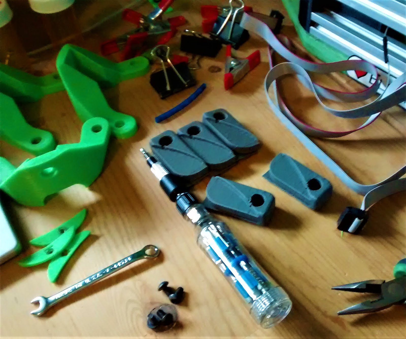
The parts are all designed to fit on my Mini Kossel's 180mm bed, each wedge takes about 2 hours with 0.2mm layers at 50% infill, so about 18 hours total for a full set of 9. For fasteners, you'll need 40 M3x16mm screws, 50 M3 nuts, and 6 M3x40mm screws for anchoring the bed layers together and to the lower frame. Assembly is fairly straightforward, I just used a screwdriver and wrench for the fasteners, along with some spring clamps to hold things in place during assembly.
Assembly tools for the print-bed support
Support half-assembled, note the use of clamps to secure parts
Fully assembled bed support
I've printed the parts in PLA, so I'm using a couple of these Pyron flame protectors for bed insulation, I've been using the same thing on my Mini Kossel for almost a year and haven't had any problems.
Cutting pattern for flame protector
Print-bed stack cross section
Once the insulation is installed, it's simply a matter of tightening the bed clamps into place with some M3 nuts or thumbwheels, I'm using these printable ones from Thingiverse.
Once the bed clamps are tightened, the only step left is to connect the thermistor and power leads to the Duet 0.8.5 and level things so the bed surface is square to the towers.
Heat-bed connectors on Duet 0.8.5
Print-bed installed and squared
And that's it for now, next time it'll be assembling the effector and Prometheus system.
After doing some research online, and getting my multimeter out to poke around at things, it turns out that this kind of power supply's outputs are very simple, two sets of three for positive and negative output linked in parallel, with the other three points being the mains input. I've also used the multimeter to fine tune the V-ref or reference voltage to exactly 24 volts, the next image summarises what's what.
Power supply outputs labeled and organized.
Once that was sorted, I powered up for a brief connection test, just to verify that everything worked properly. After getting a positive result, I started on the last of the fixed parts, the electronics cooling fans. I'm using a pair of 80mm*20mm box fans to keep the Duet 0.8.5 from overheating, they're a bit loud but produce lots of airflow. I'm using this fan grille to help keep some of the wiring out of the fan blades.
8020 fan positions around the Duet 0.8.5
That's all for this update, next time it's installing the heat-bed, so Happy holidays and see you next time.
I just finished a partial refit on my Mini Kossel, and realized that I hadn't mentioned it on here yet, so here's a brief tour of the upgrades and modifications from this past year. Most of the important ones I've made are related to the plastic handling components, so I'll cover them by following the filament path.
Starting from the top of the filament path, the first modification I added was this spool holder by Creative Tools, specifically the OpenScad remix done by GeoDave on Thingiverse. This is by far the nicest spool holder I've used to date, most of the other ones for deltas ether occupy the upper triangle completely or are just a printable stick that bolts onto the side, so this is a massive improvement over those options.
Greg's Wade's Extruder, bowden variant
After the Mini Kossel's previous MK8 extruder suffered a dulled drive gear recently, I decided to replace it with a Greg's Wade's extruder, an old and proven design from the RepRap project. I've had it running for about two weeks at this point, and it's been very solid and reliable.
E3D Lite6 nozzle
Next on our tour is one of the first upgrades I made, the E3D Lite6 hot-end. The Mini Kossel kit came with a 'metal J-head' hot-end that malfunctioned the first time I turned it on, and started oozing plastic out of every joint in the heater block, regardless of what I tried. After researching hot-ends online, the Lite6 quickly came up as a reliable and easy to use option for a beginner, and I've not looked back since.
MK3 aluminum heat-bed with Buildtak on glass topper
Finally, we come to the heated build-plate or print-bed, the foundation that everything is printed on. I started out with a MK2a PCB heater and glass combination that was included in the kit, but the heater was warped when I got it, so I sourced a MK3 aluminum heater as a replacement and I haven't had any issues with it since. The Buildtak print surface is something I started using on the Micro a few months ago, and I decided to add a sheet to one side of my glass bed after I ran out of the glue stick that previously served to improve bed adhesion. And that's my workhorse printer's key upgrades finished, for now.
Last time, I'd just finished installing the steel rod arms, but I ran into a problem with 6 of them being too heavy for the motors to hold at the top unpowered. I replaced 3 of them with wooden shafted ones after some weighing and experimentation that showed the max unpowered holding weight of all 3 motors is around 900 grams or 300 grams per motor.
Wooden rod arms being assembled
How to use 6inch/150mm calipers to measure long objects with some markings
I'd mentioned measuring the rod arms in part 4, but didn't include details on how that was accomplished. I just wrapped some small pieces of electrical tape around the rod arms roughly 1/3 of the way along from each end as reference points, then measured the lengths of each section of rod, that puts my accuracy at +/- 0.03mm, since my calipers are accurate to +/- 0.01mm. The updated average length is 396.54 +/- 0.03mm, and that finishes the rod arms.
Left to right: Power supply bracket, 5x20mm 5A fast-blow fuse, power plug/switch
After sorting out the rod arms, it was time to start on the electrical harness. I've already installed the motors and end-stops, so the power plug/switch unit is next. For wiring up one of these 'Power switch with fuse and socket' units I followed this guide by 3dSuppli.com, it covers all of the details of setting up the mains wiring correctly. For the housing, I'm using a remix of this power inlet mount, with some added extra flanges to allow it to fit on the electrical conduit with the help of a shortened variant of the alternate conduit mounting brackets from the Emmett-Delta design. The printed parts are connected with 2 m3x50mm screws and a couple of m3 nylock nuts.
Power supply wired in and ready for securing
Power supply mounted and secured
Duet 0.8.5 mounting posts
With the power supply fully installed, it's time to mount the Duet 0.8.5 onto the base and plug in the motors and end-stops. Since the Duet is designed to use function as a heat-sink for the stepper drivers, I designed some printable mounting posts to provide space for airflow under the board. Once mounted, it's mainly just a matter of plugging in the motors and end-stops to the relevant pins, which are helpfully marked on the underside of the board. It's worth noting that for micro-switch end-stops, the leads need to connect to the outer pins of the 3-pin connector, not the center and one side used on a RAMPS 1.4 derived board.
End-stop connector for Duet
Duet 0.8.5 mounted and partially wired
That's it for now, my next step is to sort out the wiring pinout for the power supply's output, so I'll be breaking out the multimeter next time for exploring what pin gives what current level, along with mounting the cooling fans, but that's for next time.
End-stop wire routing at the top of the towers
End-stop wire routing at tower base, note the zip-tie retainer on the right
Well, it's time to cover the last of the major mechanical assembly for the Proteus, building and installing the rod arms. Most deltas use carbon fiber tubing, Traxxas 5347 joints, and M4x20mm set screws for building the rod arms, but since carbon fiber tubing is a bit tricky to find locally, I'm using some 3/8" cold rolled steel that I got at the local hardware store instead. I've also designed some 3D printed end caps to allow using regular M4x20mm cap screws for mounting the traxxas joints onto the shafts.
For assembling the Traxxas joints, I used the delightful tool pictured above, it's a fairly quick print, 30 minutes and it's ready for use after adding a M3x30mm or longer screw. As for the end caps, the STL is here, I'd recommend printing them on their side since the length of the lower point is fairly critical to getting the final arm length correct. After assembling the joints, the next step was tapping both the end caps and traxxas joints with a M4x0.7 tap to make installing the screws easier.
Threading the endcaps with a M4x0.7 tap
Completed end cap assembly
After tapping, the actual assembly is fairly quick if you use a power drill to provide the rotational power, I've got it clamped in an old bench vise to make it easier to keep things aligned, but you can easily assemble things freehand with just a hand screwdriver. For the shafts, I used the same technique that I used for cutting the Mostly Printed CNC's tubing to length to cut 6 327mm sections and printed a jig for final assembly.
Steel shafts cut to length on jig for length checking
Once the jig was printed and screwed down to an old 2x8, flattest surface I had on hand, it was simply a matter of mixing some 5-minute epoxy, applying some to the ends and pushing on the end cap assemblies, then placing it in the jig and letting things slide until it fits perfectly.
Fully assembled rod arms jigged and drying
After everything was assembled and settled, I left the arms overnight to dry, and printed a customized version of this delta effector generator to use for the outer part of the effector platform. Measuring and averaging the final lengths of all 6 arms gives a center-to-center length of 396.34mm, one of the numbers needed for calibrating the Proteus when it's finished. Finally installing the arms on the rest of the frame was straight forward, just needed 12 m3x20mm screws.
Rod arms half installed
Now all that's left is to redo the printbed support and install the electronics, but that's a topic for next time.