Wednesday, 26 October 2016

Project: Proteus Delta part 2

Building the towers and assembling the frame:

Completed Proteus Delta frame
     For building the towers, the Emmett design calls for 1/2-inch electrical conduit which is fairly rigid on smaller sections, but over a 5-foot length it flexes almost 1/4-inch, more than enough for a motion wheel to slip and come loose, so I needed some method to fix the pipes together. Talking to David Bunch, the Emmett's designer, came up with the idea of gluing some printable spacers between the rods, so they functionally work as one unit and don't have room to flex away from each other.


12 tower gluing spacers, with 400% vertical scaling, freshly printed
     I've used 5-minute epoxy to glue printed parts together before, it gives a very solid bond with PLA, so I got some that's rated for bonding metal and plastic with a precision applicator tip container, makes it much easier to handle.


5-minute epoxy
Jig bracket
     Obviously, holding 19 different pieces in place and aligned needs some sort of jig, and David was nice enough to design a simple clamp for keeping the tubes aligned. I printed about 18 of them and then drew some guide lines on an old 2x6 topped sawhorse and fastened 5 of them to the top, instant jig. One thing I'd do differently if I built a second jig, is to glue the brackets onto the sawhorse instead of using screws, because I ended up with a slight curve in my towers that I had to minimize by cutting them down to 4 feet overall.


Assembled jig with half of a tower clamped for gluing
Clamp in use, 2 inch deck screws used as fasteners
     The process for using the jig is fairly straightforward, put two of the conduit sections in the jig, squaring the factory end, and then use the upper clamps to secure them. Then apply the epoxy to the blocks, placing them about 6-8 inches(15-20 cm) apart, then let things sit for about 15-20 minutes so the epoxy has a chance to set.

Closeup of tower half with tape measure for scale 

     Next, remove the upper clamps, and apply epoxy to the exposed faces of the glue blocks. Put the upper tubes into place, it helps to have two people for this stage, then loosely mount the clamps, square the factory ends to each other, then tighten the clamps until things are just snug, it's very easy to snap a clamp if you over tighten things. Lastly, slide the end clamps on to keep things square, then leave to dry for 2-3 hours. Once dry, unclamp everything and repeat for the other two towers.

End Clamp
Assembled tower drying
Finished frame parts waiting for assembly
     After all the gluing is done, finial assembly is simply a matter of inserting the towers into the corners of the bottom triangle and then putting the upper triangle on top, you might need to use a hammer to 'persuade' things a bit, but after everything is square and leveled, just use some 8-32x0.75 inch or M3x25mm screws and nuts to clamp things down and it's finished. I added a piece of 3/4-inch plywood to the top and bottom for extra strength, rigidity, and so I'd have somewhere to mount the power supply. I fastened the plywood on using half clamp brackets for 3/4-inch electrical conduit, 3 on the top, 6 on the bottom, they just snap into place and one screw is all that's needed to hold things securely. I've also added some light diagonal strapping on 2 sides using a couple pieces of air duct strapping.

Nearly finished frame
half clamp for 3/4-inch electrical conduit


      With the frame finished, next up is building the rod arms and assembling the slider/carriage units.

Tuesday, 18 October 2016

Project: Proteus Delta part 1

Or Building a large Delta from Electrical Conduit part 1:

     A couple of weeks ago, I backed DisTech Automation's Prometheus System on Kickstarter, and decided that rather than refit one of my existing printers, I'd build a new larger delta specifically for it. After building the Micro Kossel and MPCNC, I ran across the incomplete Emmett-Delta on OpenBuilds, which had some interesting ideas for using electrical conduit for the frame, rather than the usual expensive V-slot. I decided to go with a 30cm diameter build plate with 1 meter of build height, so the overall size is about 1.5 meters tall with a 50 cm per side base, making this something of a monster-sized machine.

Emmett-Delta parts waiting for assembly
     For the frame, I'm using 60 feet of 1/2 inch electrical conduit for the towers, and about 12 feet of 3/4 inch electrical conduit for the top and bottom triangles, you can see some of the 3/4 inch pieces in picture with the printed parts. On the 3D printed parts, I got in touch with the original designer, David Bunch, and he finished designing some of the missing parts so I could do a full build. For the controller, I'm using the well reviewed Duet 0.8.5 and pairing it with a 24 volt heat-bed from UltiBots, I'll have more on those in a future post.


Side bar fitted with drilling jigs
Preparing to drill with 3/16 inch bit
     For filament usage, I've gone through just over 1.5 kg so far, half of that in the lower corner brackets that clock in at 240 grams each. Once I'd finished printing the corners, cutting and drilling the electrical conduit to it's final size was next. Cutting was fairly straight forward, since I used this technique with a reciprocating saw, metal blade, and miter box. As for drilling the holes to actually bolt things together, I tried doing it by hand with a power drill and 3 days later, ended up with my holes all over the place. If I did it again, I'd invest in a drill press for faster and more accurate drilling.


Side bars waiting for installation. Note the messy holes from hand drilling
The primary assembly tools: a ball-ended hex key, and a 6" crescent wrench
     Once I got the screw holes straightened out, the actual assembly for the triangles is fairly straightforward, line up the holes, insert a bolt, loosely thread a nylock nut onto bolt, repeat at next hole. I did this until all of the sides for each triangle were loosely assembled, then went around the sides tightening each bolt in turn until all of them were snug, then gave each a tiny bit more of a twist to completely lock the frame.

Top triangle fully assembled
First side of lower triangle assembled, note the installation of the bed support bracket
    When assembling the lower triangle, it quickly became apparent that I'd need to install the brackets for the electronics and print bed during the assembly, otherwise I'd need to remove the upper bars to install them and potentially damage the alignment on one or more of the sides.

Lower Triangle fully assembled, including brackets for controller board

Brackets for Duet 0.8.5 controller with space for optional Duex4 expansion board
    Once all of the bolts were tightened, it was time to start work on assembling the towers, which I'll cover next time.

Completed triangles waiting for final assembly

Saturday, 8 October 2016

Delta 3D printer calibration the easy way

Micro Kossel and Mini Kossel
     As most readers will probably have noticed, I use delta mechanics on my 3D printers, they're fun to build, but a pain to get working perfectly. The cause of this difficulty is largely down to the calibration or getting the firmware's model of the machine to match reality. I'm going to demonstrate how to use some simple tools that make this process easy and straightforward.
Escher 3D Delta Calibration Wizard
     The tools I use for calibration are quite simple: a piece of standard printer paper, a laptop, the 3D printer, and the online web calculator created by Escher 3D (Calculator is here). You'll also need a program to control the printer's movements manually, such as Pronterface or its counterpart Repetier-host, I'll be using Pronterface, but all of this is very similar in Repetier as well. If your delta printer has 32-bit electronics (Smoothieboard, Duet variants, etc.) you'll want to log onto the web interface instead.
Pronterface waiting to connect to a printer
     First thing to do is connect your delta to your computer using the usb port, open Pronterface and hit the port button, this tells pronterface to check which port the printer is connected to, usually COM3 or COM4, and then hit the Connect button to link to the printer's electronics.
Pronterface after Connecting to the Printer
     Next, look at the console output on the right, listed near the bottom of the initial connection info will be some of your printer's current calibration data, how much varies depending on which firmware type/version you're using, I'm using the master branch of Rich Cattell's Marlin fork, simply because it implements a very comprehensive model of delta motion mechanics, which simplifies calibration by allowing you to update all of the variables with a single gcode command. The current mainline Marlin uses a couple of different commands to accomplish the same thing, but this really only affects how you send the updated calibration data to your machine.
Parameters for the Micro Kossel entered into the Delta Wizard
     Now that we've connected to the printer, next step is to tell the web calculator what firmware you're using, along with the current calibration settings on the printer, most of this is fairly straightforward, the relevant info is easy to get in RC Marlin by entering 'M666 L' into the command line in Pronterface. In mainline Marlin, the command is 'M503', which dumps all of the current configuration data, along with what commands are used to change things. You might need to look up some of the codes on the RepRap wiki Gcode page. Once all of the relevant info is entered into the web calculator, click on the 'Suggest probe points' button and the grid of boxes below will fill with some numbers, these are points to probe the nozzle height errors on your printer.


    Now it's time to use the piece of paper to actually measure the differences between the firmware's settings and reality. This is a fairly simple routine, first put the piece of paper on the print bed over the spot you want to measure. Then click the 'Home all' button, red arrow in the screenshot below, to zero the printer's coordinate system. Next, use the command line interface, green box/arrow in the screenshot below, and input something like 'G1 X0 Y0 Z 20' and click 'send' or press enter.
Pronterface with key controls highlighted
     The printer should respond by moving the nozzle to 2 cm off the bed at the center point. The reason for sending the nozzle to a point above the bed is simply to avoid damaging the printer by telling it to put the nozzle below the bed, which can happen with an uncalibrated machine. Next, use the manual jog buttons, blue rectangle and arrows in the screenshot, to lower the nozzle down, 1 mm at a time, then 0.1 mm once it's close to the bed, until the nozzle is just touching the piece of paper. It should be possible to drag the paper around with 1 finger, if not, raise the nozzle by 0.1 mm until it is. Once you've got that set, send 'M114' to the printer, it'll respond with the exact current position of the nozzle, the number in the Z column is the nozzle height error and needs to be entered into the web calculator's rightmost column, on the line that corresponds to the point being measured. Now just repeat this process until all of the nozzle error's have been measured, then click on the 'Calculate' button below the point table.
Finished Calibration Wizard
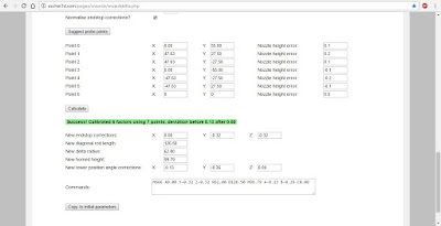
   A new line of text will appear, usually on a green background saying something like: "Success! Calibrated 6 factors using 7 points, deviation before 2.01 after 0.2". This is mostly irrelevant, only the deviation after value is of interest, the closer it is to 0 the closer to perfectly calibrated your machine is. The box at the very bottom will have a line or two of gcode, these are the commands to send to your printer to update the calibration. Simply click and drag over the text in the box until one of the lines is highlighted, then right-click and click 'copy' in the menu that pops up. Next in pronterface, right-click on the command line and click 'paste', this will copy the command from the web browser to the command line, and then click 'send'. Repeat if needed for the other lines of commands, then enter 'm500' and click 'send'. That saves the updated parameters to the printer's memory (EEPROM), otherwise it will just forget the updated calibration the next time you turn it off.
     Congratulations, you've successfully calibrated a delta 3D printer, now it's time to start making things with it.