Showing posts with label Micro Kossel. Show all posts

Saturday, 28 October 2017

Building a Prusa i3 MK2 from Scratch

Prusa i3MK2 'Sculptor"
    So, time to reveal what the mystery replacement for the Micro Kossel is, I've repurposed the electrical harness into a Prusa i3MK2 clone build. Sourcing the parts was a bit of a nuisance, but most of it had close matches at my local hardware store or was stuff I had on hand.
Imperial equivalents of the M8 (5/16") and M10(3/8")
 with 1/4" threaded rod for the z-axis screws
Idler arm for the extruder with a 625 bearing from OpenBuilds
     Now, some of the parts for this machine do require CNC cutting normally, but following some of the tricks used by Tom's 3D build from march, I printed the frame template on paper, glued it onto and cut it out from some 3/4" plywood for the frame and 1/4" plywood for the y-carriage.
3/4" plywood frame with template attached
Frame and y-carriage ready for painting
     After cutting out the wooden parts, the next step was to paint and seal them, otherwise they'd change size with the ambient humidity. I used some black acrylic for the first coat, then followed up with a coat of Varathane to seal them.


Main frame waiting for paint to dry
Y-axis parts and tools
     While waiting for the paint to dry I moved on to assembling the y-axis/base frame. Assembly is fairly straightforward, only major thing that you need to watch is that the frame is completely square and flat. Squaring the frame is fairly simple with an old woodworking trick, just take a tape measure and check that both diagonals are the same length, if they match the frame is square in that plane. As for making sure it was flat, I used the one surface in the workshop guaranteed to be perfectly flat, the top of the table saw.


Checking the diagonals for squareness
Checking the other diagonal
     Once that was assembled, the next step was adding the vertical frame, then installing the x/z-axis assembly followed by the extruder carriage to complete the primary frame assembly.


Main frame assembled
Extruder ready for installation
    With the Extruder installed, it was time to sort out where to mount the main control boards. The normal place for them is on the back left of the main frame, but the cables on the LCD module I'm using are only 10cm long, so I've mounted the Ramps package on the front left side with the power block on the back.

Installing the Ramps casing (Thing:761806)
Power brick with custom brackets
Raspberry Pi Zero W for Octoprint host
    I designed a couple custom L-brackets for mounting the power supply and Pi camera, with those installed, it was time to sort out the firmware and calibrate the z-height. For the print-bed, I'm just using a sheet of Buildtak stuck to some 3/8" plywood, basic but workable.

Completed i3MK2

Thursday, 28 September 2017

Decommissioning the Micro Kossel

Micro Kossel
    After almost 18 months of heavy use the Micro Kossel was long overdue for maintenance and wear checking, so I decided to partly disassemble it last week, this unfortunately lead to the discovery of several fatal flaws that would have required basically replacing the frame to correct, so I decided that it was time to retire it.

Micro Kossel parts after disassembly
    Most of the flaws were wear and tear issues that some of the PLA parts hadn't stood up to well at all, specifically the AMZ3D transparent red carriages and SEACANS.com green rails and corner/motor brackets. I don't have photos but the motor corners were warped badly enough that the motors were stuck pointing about 20 degrees up from the normal horizontal position, making any attempt to tighten the drive belts pointless, they'd just slip off the mounts or the plastic would just melt further and worsen the problem over time. 

Micro Kossel frame rail with cracked section

Micro Kossel frame rails with cracked sections
     As you can see, the Seacans green PLA fractured across the layers on these sections, a highly atypical failure for a printed part, normally you'd see fracturing along the layer lines with PLA, not this glass-like fracturing. It's worth noting that the Tinkerine Lavender PLA shows only minor damage where stuck nuts and bolts were removed, and that's mostly cosmetic, so I'll probably be reusing those parts in a future project. 

Carriage plate showing stress fractures
    The AMZ3D PLA carriages are by far the most alarming of the parts, two of them cracked at the hinge point (lower left of the image above), and all three where showing some alarming stress fractures that you can just see in the picture above, I've warped the contrast to make it a bit clearer, my camera has a hard time seeing them but they're very clear to the naked eye. Taken together, these issues mean that it was just a matter of when, not if, that the hot-end would come off axis during a print and make a complete mess at minimum, start a fire at worst, so I've dismantled the frame and salvaged the electronics for a new project, here's a preview, but more on that next time.

Mystery parts for next project

Monday, 3 April 2017

Safety Upgrade: adding an air filtered enclosure to a 3D printer

Micro Kossel moving into new home
     After reading the 3Ders.org article on 3D printers with enclosures and filters reducing particle emissions, I decided to relocate and re-house my existing printers for safety's sake. I've moved the Mini Kossel out to my garage workspace for the moment, more on that another time, and the Micro Kossel got a new housing. 

Micro Kossel's new housing with intake fan installed
     Drawing inspiration from the method of refitting a plastic bin with air seals for storing moisture sensitive filament (example video), I went about tracking down a plastic bin deep enough for the Micro Kossel to fit inside. And since the original article mentions using a hepa filter that is rated for filtering hydrocarbons, I tracked down some normally meant for use on a workshop filter mask. 


Hepa Filters and 60mm fan
    Add to that a couple of 60mm fans, a roll of aluminum tape, some stick-on foam weather-stripping, and a couple of printed adaptors to complete the parts list. Tools are a drill with a 2.5inch pocket hole jig/blade, the aluminum tape, a 1/8th inch or 4mm drill bit, and a pair of scissors or cutters for trimming the foam striping to length.


Foam weather-stripping
One of the filters unboxed
     The first step was to put a strip of the foam tape along the rim of the bin, followed by using one of the fans to mark out where to drill the holes in the sides. After doing that, I measured the dimensions of the filter and designed a printable mounting bracket to interface it with the exhaust fan.


Foam seal installed on bin with spare parts in background
Filter mount on the exhaust fan
Filter retainer ring
    The STLs are available here, they will probably only work with that specific brand of filter, but should be a useful reference regardless. While that was printing, I used the pocket hole bit to make openings for both the input and output fans.


Fan mounting hole with points for screws drilled out.
    After the holes were drilled, it was a simple matter to bolt the fans into place with some spare #6 screws that I had leftover from building the MPCNC, although M4 screws would probably work just as well.

Filter installed and secured with aluminum tape
    For securing the fans, I had planned to use elastic bands to hold the retainers in place, but remembered that I had some Aluminum tape left over from another project, and since it's normally used for sealing holes in air ducts, I decided that wrapping the joints with some couldn't go amiss. 

Power lines for the fans
    Finally, it's just a matter of wiring up the power to the fans. I've got the Micro Kossel fitted with a 2.1mm barrel jack for power, so I just got a couple of spare connectors and created an in-line patch cable that basically just hooks the fans in parallel with the printer itself, turn the printer on and the fans come up automatically.

Saturday, 8 October 2016

Delta 3D printer calibration the easy way

Micro Kossel and Mini Kossel
     As most readers will probably have noticed, I use delta mechanics on my 3D printers, they're fun to build, but a pain to get working perfectly. The cause of this difficulty is largely down to the calibration or getting the firmware's model of the machine to match reality. I'm going to demonstrate how to use some simple tools that make this process easy and straightforward.
Escher 3D Delta Calibration Wizard
     The tools I use for calibration are quite simple: a piece of standard printer paper, a laptop, the 3D printer, and the online web calculator created by Escher 3D (Calculator is here). You'll also need a program to control the printer's movements manually, such as Pronterface or its counterpart Repetier-host, I'll be using Pronterface, but all of this is very similar in Repetier as well. If your delta printer has 32-bit electronics (Smoothieboard, Duet variants, etc.) you'll want to log onto the web interface instead.
Pronterface waiting to connect to a printer
     First thing to do is connect your delta to your computer using the usb port, open Pronterface and hit the port button, this tells pronterface to check which port the printer is connected to, usually COM3 or COM4, and then hit the Connect button to link to the printer's electronics.
Pronterface after Connecting to the Printer
     Next, look at the console output on the right, listed near the bottom of the initial connection info will be some of your printer's current calibration data, how much varies depending on which firmware type/version you're using, I'm using the master branch of Rich Cattell's Marlin fork, simply because it implements a very comprehensive model of delta motion mechanics, which simplifies calibration by allowing you to update all of the variables with a single gcode command. The current mainline Marlin uses a couple of different commands to accomplish the same thing, but this really only affects how you send the updated calibration data to your machine.
Parameters for the Micro Kossel entered into the Delta Wizard
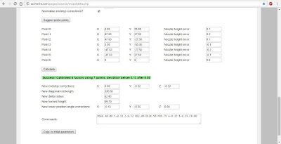
     Now that we've connected to the printer, next step is to tell the web calculator what firmware you're using, along with the current calibration settings on the printer, most of this is fairly straightforward, the relevant info is easy to get in RC Marlin by entering 'M666 L' into the command line in Pronterface. In mainline Marlin, the command is 'M503', which dumps all of the current configuration data, along with what commands are used to change things. You might need to look up some of the codes on the RepRap wiki Gcode page. Once all of the relevant info is entered into the web calculator, click on the 'Suggest probe points' button and the grid of boxes below will fill with some numbers, these are points to probe the nozzle height errors on your printer.


    Now it's time to use the piece of paper to actually measure the differences between the firmware's settings and reality. This is a fairly simple routine, first put the piece of paper on the print bed over the spot you want to measure. Then click the 'Home all' button, red arrow in the screenshot below, to zero the printer's coordinate system. Next, use the command line interface, green box/arrow in the screenshot below, and input something like 'G1 X0 Y0 Z 20' and click 'send' or press enter.
Pronterface with key controls highlighted
     The printer should respond by moving the nozzle to 2 cm off the bed at the center point. The reason for sending the nozzle to a point above the bed is simply to avoid damaging the printer by telling it to put the nozzle below the bed, which can happen with an uncalibrated machine. Next, use the manual jog buttons, blue rectangle and arrows in the screenshot, to lower the nozzle down, 1 mm at a time, then 0.1 mm once it's close to the bed, until the nozzle is just touching the piece of paper. It should be possible to drag the paper around with 1 finger, if not, raise the nozzle by 0.1 mm until it is. Once you've got that set, send 'M114' to the printer, it'll respond with the exact current position of the nozzle, the number in the Z column is the nozzle height error and needs to be entered into the web calculator's rightmost column, on the line that corresponds to the point being measured. Now just repeat this process until all of the nozzle error's have been measured, then click on the 'Calculate' button below the point table.
Finished Calibration Wizard
   A new line of text will appear, usually on a green background saying something like: "Success! Calibrated 6 factors using 7 points, deviation before 2.01 after 0.2". This is mostly irrelevant, only the deviation after value is of interest, the closer it is to 0 the closer to perfectly calibrated your machine is. The box at the very bottom will have a line or two of gcode, these are the commands to send to your printer to update the calibration. Simply click and drag over the text in the box until one of the lines is highlighted, then right-click and click 'copy' in the menu that pops up. Next in pronterface, right-click on the command line and click 'paste', this will copy the command from the web browser to the command line, and then click 'send'. Repeat if needed for the other lines of commands, then enter 'm500' and click 'send'. That saves the updated parameters to the printer's memory (EEPROM), otherwise it will just forget the updated calibration the next time you turn it off.
     Congratulations, you've successfully calibrated a delta 3D printer, now it's time to start making things with it.

Friday, 16 September 2016

Micro Kossel effector upgrade part 4

After about 2 months of heavy usage, the version 4 effector suffered the same bending damage that affected version 3, so I've redone the platform and moved the ducting to a screw-on skirt instead of inside the effector.

Version 5 assembled 
     Another issue that cropped up with version 4 was part of the upper fan mounts had a tendency to catch against the rod arms when printing near the outer edges of the printbed, so I've moved them upward by a couple of centimeters for version 5.

Version 5 being used to print 'Marvin'
    I've printed a few things with the version 5 effector so far, and it's much better than the old version 4. The STL's are available on Thingiverse (thing:1726397), and you'll need a couple of M3x10mm screws to attach the skirt after printing.

Monday, 29 August 2016

3D printer tips and tricks

One of the constants of designing and building kit or custom 3D printers is the continuous 
exploration of ideas and changes to make things work more effectively or more robust and reliable. I started my 3D printing journey last september with a basic Kossel kit printer, and I've been reworking and refining parts of it ever since. I've compiled some of the better and current modifications below, along with some tricks that I've found that make working with the printers easier.


Micro Kossel Extruder
Mini Kossel Extruder
     First up on my tour of modifications is the extruder module, probably one of the most critical parts of a 3D printer. There are literally hundreds of different designs available online, both DIY and commercial, but the one I'm using is the Prusa/Makerbot MK8, which is available online as an aluminum kit. I've modified mine with a stainless steel MK8 drive gear and a M6 pneumatic fitting that I've drilled out with a 5/32 inch bit to allow the 4mm bowden tube to reach the drive gear, it makes loading the filament much easier and allows for the use of flexible filaments as well. The other change I've made is to add a M5x10mm bolt(found at the local hardware store) to the spring to allow for higher compression, this helps grip the filament better and makes handling some of the cheaper brands easer.


Masking tape, BuildTak, UHU glue and a palette knife on my Mini Kossel build plate
     Next is bed adhesion techniques. I've only worked with PLA, so most of this probably doesn't apply to the more unusual filaments. For printing without a heat-bed, I've used masking tape, plain and with glue stick on top, works fairly well but degrades quickly and doesn't work for parts with small footprints. Best unheated surface I've used to date is 'Buildtak', a branded PEI film sheet material, it comes in 3-packs in a variety different sizes, and according to the literature, most types of filament will adhere to it without any difficulty. For heated beds, I'm currently using lightly applied UHU glue stick on 3mm glass at 45 Celsius for PLA, provides good adhesion and lets go easily if you put the glass and print in the freezer for about 10 minutes to let things cool, just remember to wash the glass every 10 prints or so, otherwise the glue will eventually build up to the point that the print gets nearly permanently stuck on the build plate. If a print does get stuck, clamping the glass firmly to a solid anchor and applying a 5-inch putty knife to the bottom of the print with a hammer can usually fix the problem.

     Last up are a couple of Delta specific tips, a simple way to measure delta rod arm length and a simple add on that drastically reduces the noise generated by the printer. 


Measuring delta rod arms for exact length step 1
Measuring Rod arms step 2
     I recently had to rebuild the rod arms on my Mini Kossel, turns out that carbon fiber tubing will strip out over time if threaded ends are used. Regardless, I had to make a quick jig to get the lengths mostly the same, and I had a bunch of Lego bricks laying around, so I drilled a couple of holes for some M3 screws, and built the jig using one arm dry assembled to set the approximate length. After the jig was finished, I used some five-minute epoxy to lightly coat the threaded parts of the rod ends and used the jig to get them to approximately 
the correct length. After everything had dried, I rejigged each rod and used a spare Lego brick and my 6" calipers to measure the exact length of each arm. The spare Lego brick acts as a marking block, providing a point of reference for the calipers, since the arms are roughly 8.5" long. 


Vibration damping feet
     And lastly, I found these useful little vibration damping feet while browsing Thingiverse. They're quick to print and easy to install, and the difference was immediately noticeable when starting my next print after installing them on the Micro Kossel, it's now very quiet and bumping the table doesn't disturb things at all.

Tuesday, 5 July 2016

Micro Kossel Upgrade, Part 3

And now for the 3rd and final update on this project. After my last post, the version 3 effector warped during a 15 minute test print, so it was back to the drawing board for revisions. This time the solution was fairly simple, I just raised the bottom of the effector to be parallel with the bottom of the heat-sink and added some mounting holes for the heat-sink fan to the clamp section since the E3D duct won't fit on this version.

Micro Kossel with V4 effector installed.
Raised Effector V4 printed parts

Assembly and installation is mostly the same as for the V3 design, only change is that only the upper mounting holes for the clamp are used, the lower ones were removed to allow space to install the 3010 mm fan properly.

Non-printed parts:
1 E3D v6 or Lite6 hot-end
2 3010 mm box fans with 2 corners removed
4 M3x20mm screws
Kapton tape


V4 with Hot-end and Fan installed

I've been printing for over 14 hours with the V4 effector and it's worked flawlessly with no failed prints so far. Overall print volume is currently 10 cm tall by 11 cm diameter, which is exactly what the Micro's original design concept envisioned.


V4 effector with all fans installed


The STLs to build this upgrade can be downloaded from this post: 
V4 Clamp 
V4 Raised Effector Body